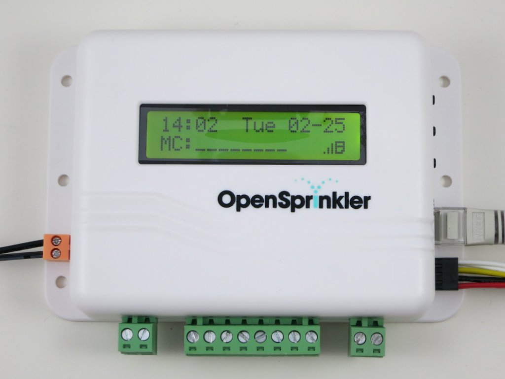
Update: check out our new standalone OpenSprinkler Bee (OSBee) 2.0 with built-in WiFi and OLED display.
It has been a month since my last post. Apologies for being silent for a month. In the meantime a lot of new exciting projects are happening. Today I am going to show you the first prototype of OpenSprinkler Bee (OSBee) — a programmable sprinkler timer for battery-operated valves.
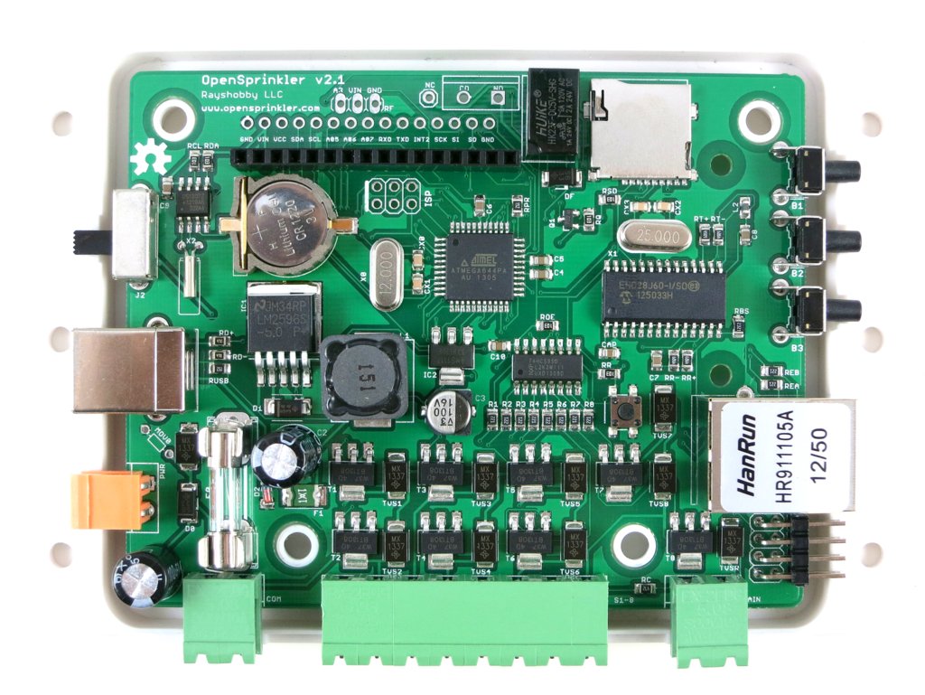
Like the classic OpenSprinkler, OSBee is an open-source Arduino-based sprinkler timer. The main difference is that OSBee is designed to work with battery-operated sprinkler valves. It’s powered by two AA batteries. In contrast, the classic OpenSprinkler is powered by 24V AC wall adapters. Also, OSBee does not have built-in Ethernet interface, but it has a 2.4G RF transceiver (nRF24L01) and I am considering leaving spaces to add additional modules such as XBee and Bluetooth. This way OSBee can communicate with a base station or a smart phone, for creating web or smartphone-based user interface.
The name ‘Bee’ comes from the abbreviation Battery-Enabled Extension. It’s co-incidence that it sounded more like XBee. It may very well have an XBee slot in the end, but the name was not intended to imply XBee. Also, ‘Bee’ reminds me of the garden, and gardens need to be watered, so, there is the connection. Different from the classic OpenSprinkler, OSBee now comes with a water-proof enclosure, which means it can be left outdoors, such as in a garden, and will do its work diligently, like a Bee 🙂


The history of OpenSprinkler Bee traces all the way back to my very first Arduino-based sprinkler timer project — the Minty Water Valve Controller. It is a wireless sprinkler timer that is small enough to fit inside a mint tin. That was summer 2010 and I was shopping for a sprinkler controller for my new installed lawn. I was starting to learn about Arduino and had this great inspiration to design and make my own sprinkler controller using an Arduino 🙂 There I made it, and I posted a video about it (see below).
It was soon spotted by Chris Anderson, currently the CEO of 3D Robotics. We then started collaborating on the OpenSprinkler project. After some market research, we figured out that most common household sprinkler systems (particularly underground sprinkler systems) use the 24V AC sprinkler valves. That’s why instead of focusing on battery-operated valves, we started designing the classic OpenSprinkler for 24V AC valves. But battery-operated sprinkler valves are also very useful — they are power-efficient, most of them can be hooked up with garden hoses so they are very mobile — you can move them anywhere you have watering need. So far forward four years to now, after releasing the classic OpenSprinkler and its variants OSPi and OSBo, I’ve finally decided to finish up what I started a long time ago, that is, the OSBee!
Technical Details
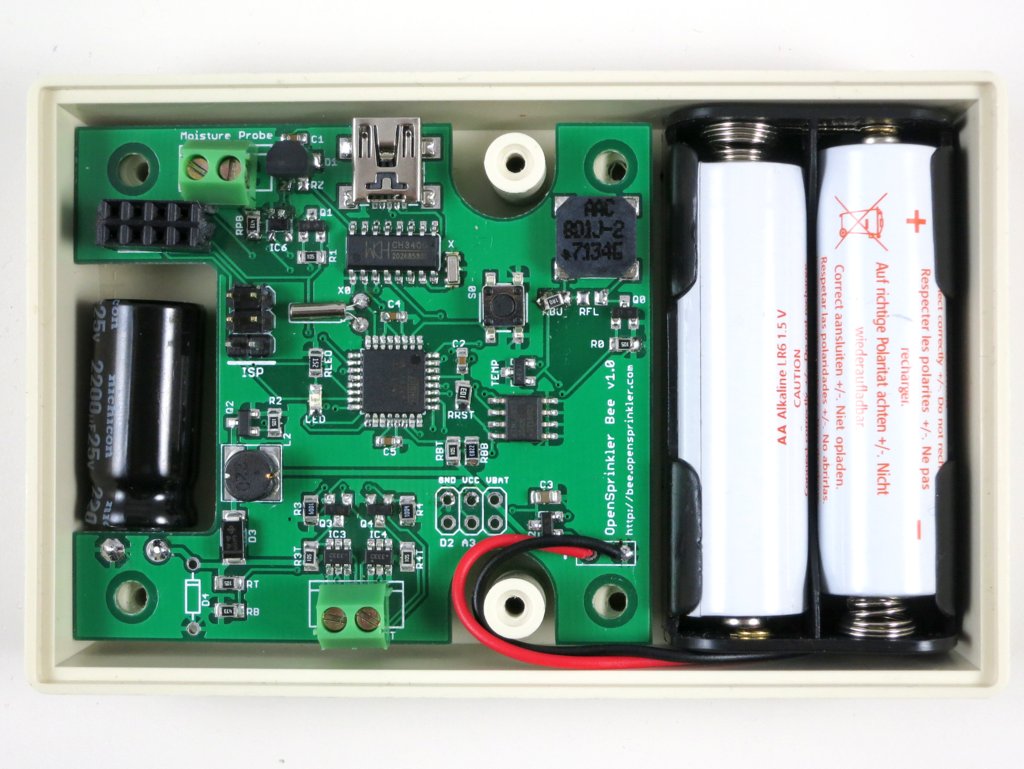
For the technical minded, here are some details about the prototype design:
- ATmega328 microcontroller, classic Arduino stuff 🙂
- Powered by two AA batteries, which are boosted to 3.3V VCC using Microchip’s MCP1640 (same design with first-generation AASaver). MCP1640 has a bypass mode, allowing it to turn off boosting when microcontroller is sleeping. This way it can maximally save power.
- nRF24L01 2.4G RF transceiver. This is one of the most popular and lowest-cost RF transceivers. This chip has excellent operating voltage range (1.9V to 3.6V) and reasonable transmission range (up to a couple hundred meters?). It also has a version with amplification which can extend the transmission range to a kilometer!
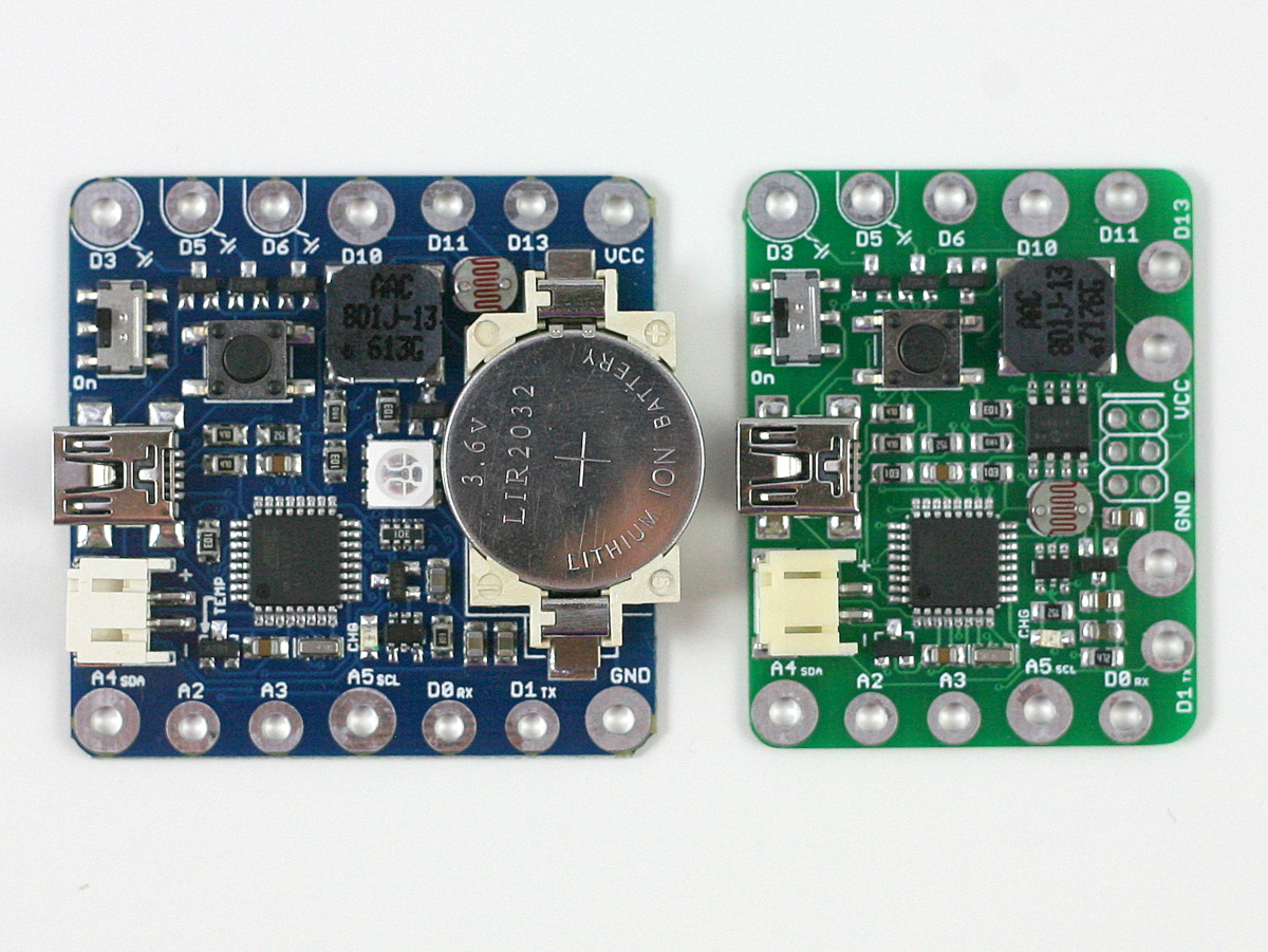
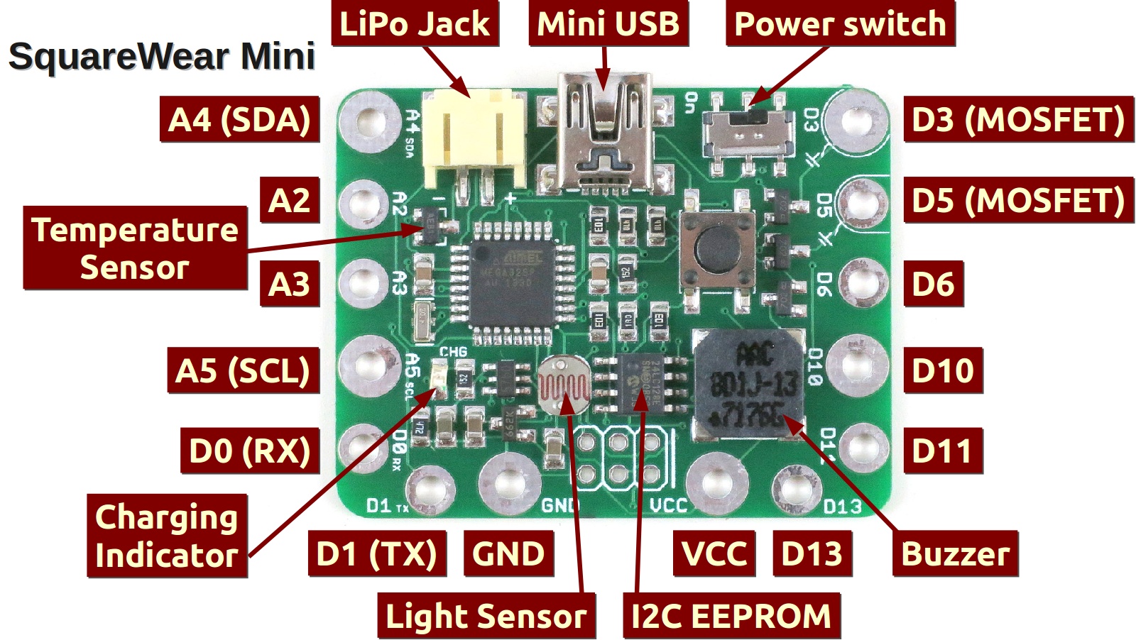
- SMT buzzer, push-button, 16KB EEPROM (borrowed from SquareWear 2,0 and Mini design)
- PWM-driven boost converter with software defined boost voltage, and an H-bridge to drive sprinkler solenoid. This allows OSBee to interface with many types of valves at different operating voltages, such as 9V, 12V, 24V.
- Soil moisture sensor using a capacitive soil moisture probe and a Schmidt trigger oscillator to measure capacitance. This will provide OSBee with the capability of soil moisture based control.
- Serpac 121 enclosure with water-proof perimeter seal.
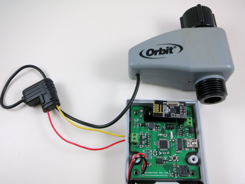
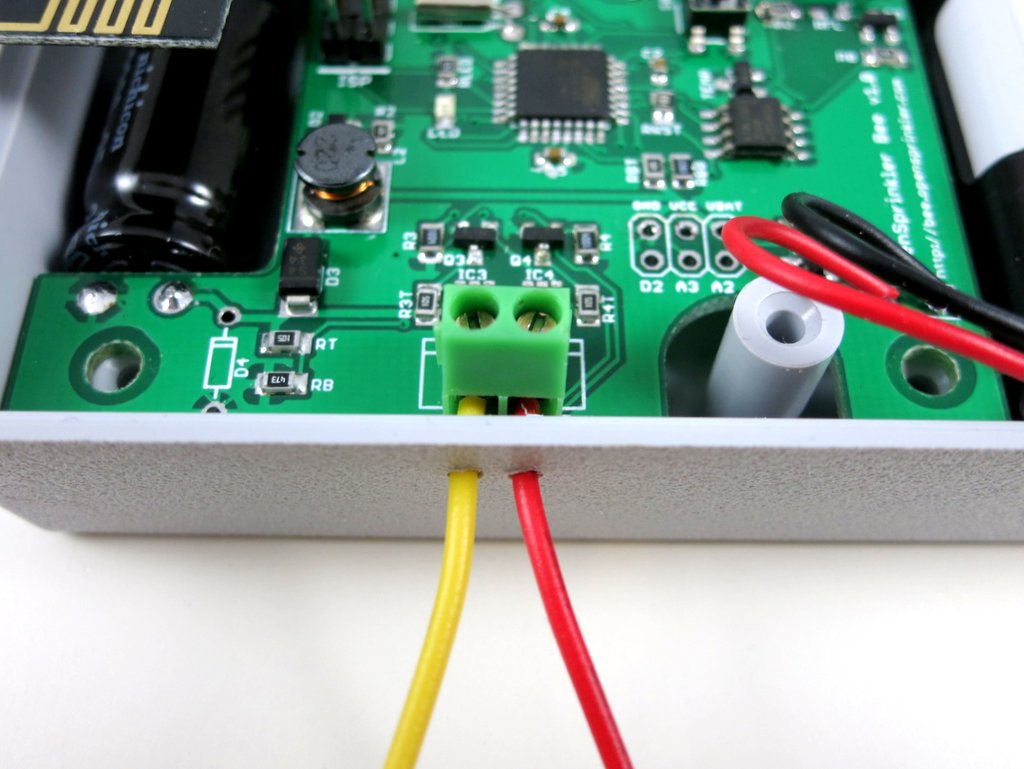
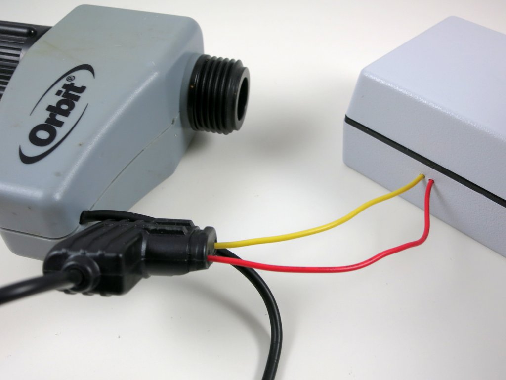
One tricky part with preserving the water-proof design is how to make the connection from the controller to the sprinkler valve. To lower the cost, I have to stick with off-the-shelf enclosures, which means minimal customization. The current solution I figured is to simply drill two small holes and insert two wires through the holes. Then you can seal the holes with some hot glue or water-proof spray. Not the most elegant solution, but simple.
Also, the choice of AA batteries (as opposed to rechargeable Lithium batteries) is due to the consideration that the controller may be left outdoor during hot summer days. In this case the temperature can potentially rise up to 60 degrees Celsius, which is very unhealthy to Lithium batteries.
So there you go, the first prototype of OpenSprinkler Bee. I am in the process of finalizing the design. Comments and suggestions are much appreciated!


.JPG)