Time flies. Yesterday was day 3 of my visit to Shenzhen. I went back to SeeedStudio and worked with the engineers on improving the design we talked about during day 1. Here I will give you a sneak peak preview of what’s happening.
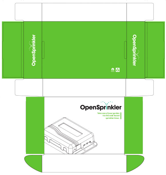
First, we are going to design a paper box for OpenSprinkler. The design is largely based on SeeedStudio’s classic paper box, with art work and color adapted to OpenSprinkler. The first prototype is shown below. It’s pretty simple but it looks pleasant. I should mention that we are designing the paper box mainly because we would like to make this more towards a commercial product, for example, a product that you may find on Amazon.com. So we need proper packaging to give it the professional look and feel. But don’t worry, it will remain an open-source product — no matter how commercial it may be, the open-source nature won’t be lost.
Next, we are also designing an injection molded enclosure for the OpenSprinkler Zone Expansion Board. As the circuit design of the zone expansion board has more or less finalized, I think it’s time to make a custom enclosure for it as well. I don’t have a copy of the prototype design yet, but one of the main changes is that the new expansion board will fit 16 stations per board, and yet the size is approximately the same as the current expansion board (which fits only 8 stations per board).
If you are wondering what about OpenSprinkler Pi — we won’t be designing an injection molded enclosure for OSPi yet, mainly because I heard from grape vine that there will be another round of revision for Raspberry Pi, and I have been advised not to finalize the design yet. On the flip side, I am working on a BeagleBone Black version of OpenSprinkler (for now, let me refer to it as OpenSprinkler BeagleBone). It occurs to me that BeagleBone Black is probably a more suitable platform for sprinkler applications, particularly because it has built-in ADC and RTC. This would make the extension board design really simple. The circuit should be very straightforward, but I do have to spend some time re-working the enclosure design. Will keep you updated about the progress.
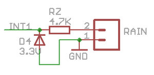
With respect to hardware revision of OpenSprinkler v2.0, there will be a couple of minor changes to address some of the engineering issues. One is a circuit-side protection to prevent the users from damaging the mcu even if they plug in 24VAC into the rain sensor port. This is a rare situation, but because the rain sensor port uses the same type of terminal block as 24VAC, a careless mistake will clearly fry the mcu. The simplest solution we came up with is to add a zener diode and a resistor to the rain sensor port, such that even if you apply 24VAC to the port it won’t damage the mcu’s pin. See the circuit diagram on the right above.
This is fairly standard, so I won’t dwell much on it. But I do want to mention that the resistor RZ should be selected carefully. On the one hand, it should limit the current through zener diode D4 when 24VAC is applied to the terminal. Assuming the zener diode can sustain 10mA, and the maximum instantaneous voltage is 40V DC, RZ should be no smaller than (40-3.3)/0.01 = 3.7Kohm. On the other hand, the rain sensor port has to preserve its normal function, which is to sense the connection / disconnection of the rain sensor. Because we make use of AVR’s internal pullup resistor, which is approximately 20Kohm, in order for the mcu to detect that pin 2 on the terminal is shorted to ground (pin 1), the resistor RZ should be chosen such that 3.3 * RZ / (20K + RZ) < 0.6 where 0.6 is the maximum voltage that appears as a logic LOW to the mcu. So RZ should be smaller than 5.2Kohm. Combining the two factors together, I've chosen RZ to be 4.7Kohm, which falls in the range in between.
Another minor change in the plan is to add a few components for AC current sensing, in order to detect the AC current supplied to the solenoids. This is useful for two purposes: one for detecting defective solenoids (i.e. current draw exceeds the typical current draw of a typical solenoid; the other purpose is for monitoring the number of valves that are currently open, which can be done by simply checking the total current draw. In any case, this will be a fairly simple thing to add to the revised circuit.
At the end of the day, a friend of mine and I went to a traditional Beijing style hot pot restaurant. Instead of using an electric burner, the traditional style hot pot uses a pot that runs on burning charcoal. It gives the food a nice 'smoked' taste, which is what you won't find in standard hot pot. The food was delicious, and I highly recommend trying it, at least once in your life :) So much for the report today. More to follow tomorrow!