Feed on
Posts
Comments

Recently I was looking for a cheap 16×2 LCD, and I found several interesting models on eBay that come with great price. I purchased one with blue backlight. The total is only $3.49 including shipping. The product was shipped from Hong Kong, so it took about 2 weeks to arrive. Here are two images of the front and the back:

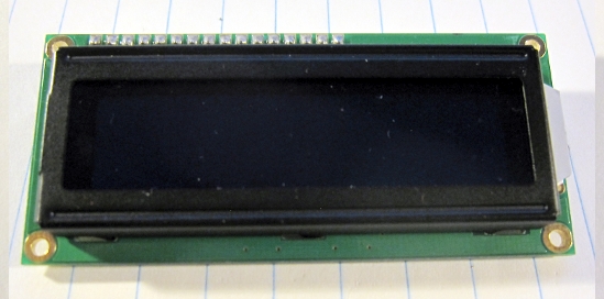
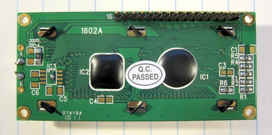
The model number is 1602a and the spec is easy to find online by searching the model number. It’s HD44780 compatible, so it can work directly with the Arduino LiquidCrystal library. The blue LED backlight looks quite pleasant. Here is an example:

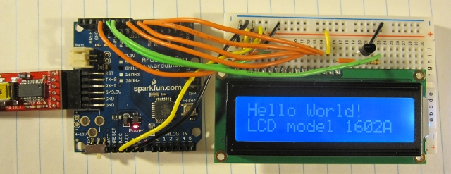
One downside is that the back LED is a bit noticeable (see the glow on the right edge of the display); also, the text will be almost completely invisible if the LED is turned off, so the LED has to remain on, consuming more power.

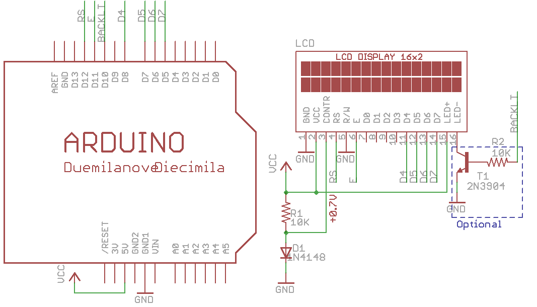
Making it work with Arduino is straightforward by following the LiquidCrystal example. I made small changes to the pin assignment. Here is what I did: LCD RS, Enable, D4, D5, D5, D6 pins are connected to Arduino pin 12, 11, 8, 7, 6, 5 respectively. Normally the display contrast (V0) pin of the LCD is connected to a potentiometer in order to adjust the contrast voltage. After some experiment, I found that the desirable voltage is about 0.65V, which can be supplied by the forward bias voltage of a standard diode, such as 1N4148.

In order to control the back LED brightness, I made use of a transistor (2N3904) and Arduino’s PWM (pulse width modulation) to adjust the effective voltage supplied to the LED. The transistor serves as a current sink, and its base is connected to Arduino pin 10 to apply PWM control. This is very standard design, refer to the schematic below. With this, I can easily control the brightness of the backlight. Just to demonstrate it, I wrote a simple program based on the Scroll example provided in Arduino. The program scrolls text left and right, meanwhile I use a timer interrupt to brighten and dim the backlight. See the video below.

Some ghosting artifacts are noticeable as the words move left and right. The video probably exemplified them, the actual LCD looks better than the video.

Update: It’s ok to connect Arduino pin 10 directly with LED- or LED+ to supply the PWM signal without using a transistor. Arduino’s I/O pins can source or sink more than 20mA of current, which is sufficient to drive the backlight LED. Other microcontrollers might not be able to do so directly from their I/O pins.

In summary, this is an decent and inexpensive LCD, which works nicely with Arduino. Right now it occupies 7 Arduino pins (1 of them has to support PWM), but this number can be reduced to 3 by using a shift register. The schematic and source code for the example program are attached below. Comments and suggestions are welcome!

Download Arduino source code lcd1602a.pde.


Tags: , ,

A New Home for Blog

After being silent for a long time, I decided to resume my blog, and as a new start, I have moved my blog from Google blog to hosted WordPress. One reason for the move is that I plan to expand the blog into a more full-featured website in the near future; the other reason is that Google blog feels very sluggish for viewing (i.e. scrolling up and down), and WordPress is much faster. I was happy to find that WordPress can import Google Blogger posts (together with comments). This way I feel I didn’t lose the history. Some new projects will be coming up soon. Stay tuned!

WordPress icon

As described in my previous blog about the first-time experience with the Makerbot, we encountered a problem where the extruder motor would stop moving after a while. Apparently there have been many discussions about this issue, such as here, here, and here. It seems to be generally agreed that the problem originated from the suboptimal performance of the extruder motor, particularly that its resistance can drop to close to 0 during operation, causing an overload current that fails the H-bridge (A3949) on the extruder controller board. I tried connecting a small power resistor in series with the motor and it still failed after a while.

The most commonly used solution seems to be the relay fix by rwensley. This allows the extruder motor to be powered directly from the +12V supply line, avoiding the failure of A3949. But the downside of a relay fix is that PWM is disabled, thus the feed speed cannot be fully controlled. So I started thinking about a MOSFET based fix. The first version is to use a single MOSFET (IRF510) in the place of relay, and this allows the motor to only move forward (which often suffices). The schematic is shown below:

The 1K resistor R1 is a pull-down resistor (1/4W is sufficient). Its value turns out to be important, because the on-board A3949 H-bridge seems to have a pull-up resistor of about 70K. Thus even when the H-bridge is inactive, the motor ports (1A and 1B) are pulled up to +12V, which must be pulled down to well below 2V in order for Q1 (IRF510) to remain off. The 1K value works perfectly (if the value is too large, it won’t be able to pull the voltage low enough). The reason IRF510 works is because it allows a high current (20A pulsed) to pass through it, which is much larger than what the A3949 chip can handle.

Using MOSFET, the main benefit is that the PWM works, hence the motor feed speed can be controlled and tuned in order to print out fine details of a 3D model. I was able to print several models with great details that I wasn’t able to achieve when PWM had to be fixed to 255 all the time.

After the single MOSFET solution worked, I started thinking how to make the motor move backward as well. It looked like the simplest way is to reproduce an H-bridge using 4 MOSFETs. The schematic is shown below:

It’s basically one of the standard H-bridge implementations. Q1 and Q4 are N-channel MOSFETs and should use IRF510 or any alternative(STP16NF06, RFP30N06LE etc.) that supports at least 10A drain-source current; Q2 and Q5 are similar but P-channel, and should use IRF9530 or any suitable alternative (STP12PF06, FQP27P06 etc.)

Note that there is no special mechanism here to handle shoot-through, which is a known issue for H-bridge design. But in this case, even if shoot-through happens, it will be over a very short period of time, and the MOSFETs are able to handle a high impulse current if that happens. I’ve tested the circuit in continuously printing for several hours and have not encountered any problem. Also note that the kickback protection diodes are ignored as the MOSFETs already have built-in diodes. Here is the small protoboard with all components soldered on it:

With this fix, the extruder motor can now move forward and backward, and PWM works in both directions! I’ve seen in several places that eventually the extruder motor should use a stepper as it provides much better control. But before that happens, I am sticking with my fix for now.

Tags: , ,

I tried to print out a scanned angel model. The details are a bit weak given the Makerbot’s resolution. But it makes a nice decoration for the bot.

Two additional photos:

Tags:

At the MakerFaire two years ago, I saw Bre Pettis demonstrating the first generation of Makerbot. I got fascinated, and since then I’ve always hoped to find a reason to buy one. Fortunately, a few weeks ago one of our projects needed 3D printed objects, and we had a chance to place an order of the Cupcake CNC Ultimate kit before it went out of stock. I heard many orders were placed, and we would like to thank Ethan at Makerbot Industry for his great help in assisting us with the ordering.

Assembling the Makerbot is an enjoyable task but requires skills and persistence. It took us two days to put everything together and get the device running. Here is a nice picture of the bot:

It really looks adorable. Now, that being said, keeping it to running stably turned out to be a quite challenging task, and there were several engineering issues we encountered. I am documenting these issues and the ways we solved them, in case they may help other Makerbot owners.

The first issue we encountered was that the extruder motor was not operating properly. Sometimes it would run for a few seconds then stopped rotating. I was very puzzled by this at first, but after looking around for a while, I noticed that when it stops, the motor’s resistance drops to 2.6 ohm, which is way below normal (should be around 45-50 ohm normally). I suspect that it may be due to the motor brush running across a specific point that corresponds to a low resistance state, and normally due to the inertia it would pass that point immediately. But in this case, it seems the h-bridge that is driving the motor is not capable at handling the instant large current, causing the motor to stop eventually. After searching online for a bit, I found the extruder relay fix by rwensley, and we made a simpler version of the fix, assuming that the motor will only move forward and never backward. The fix involved an extra 5V relay, and 2 resistors that serve as voltage dividers to adapt the h-bridge’s 12V to 5V for driving the relay. This has nicely fixed the extruder problem. I think a better option should be to use a more powerful h-bridge, or use a separate MOSFET driver. In any case, for now the quick and dirty fix works (see the picture below).

The second issue we encountered was that the heating unit of the automated build platform (abp) did not function — it was simply not turning on the heating power. We thought of many potential causes of it, but none of them was correct. Eventually we noticed that the LED corresponding to the heating unit output never lit up, and this allowed us to quickly nail down the problem to the NIF5003 MOSFET. After testing, we found it’s defective. This came as quite a surprise: a component on the extruder driver board is dead on arrival?! This was a hard find! I didn’t have an NIF5003 replacement, but a quick look at the schematic reveals that this MOSFET is only used to drive a 12V relay, so it should be replaceable by a standard MOSFET like IRF510 (which I have tons of). Once we identified this, the fix was easy. The IRF510 is largely pin compatible with NIF5003 (even though the latter is a SMD component). After replacement as shown in the picture below, the heating unit worked like a charm.

The last issue that got really annoying was the z-axis motor making a gigantic noise and skipping steps. We found that this was due to the overly tightened screws and one solution I found online seemed to suggest that one platform screw should be released and ignored just to remove the over-constrained tension force. I was doubtful about this fix, but to our great surprise, this actually worked! No more loud noise and no more z skipping!

At this point the device is basically functioning properly. There are still a couple of small issues we need to fix, such as the heated abp not being able to stick the objects onto the platform. But overall we are able to print some nice 3D objects and are enjoying playing with them. So much for our first-time experience with the Makerbot!

Tags: , ,

« Newer Posts - Older Posts »