Feed on
Posts
Comments

It has been a while since I updated my blog. Things have been quite crazy the past few months, but now I am back alive writing more blogs sparingly.

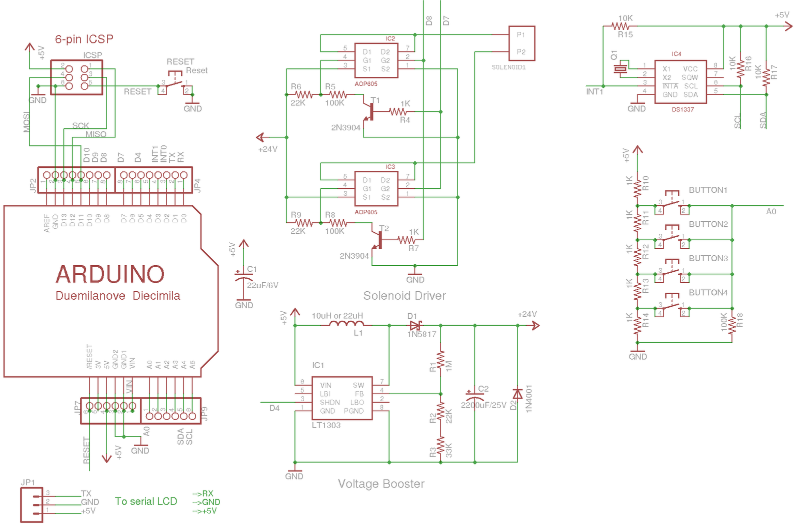
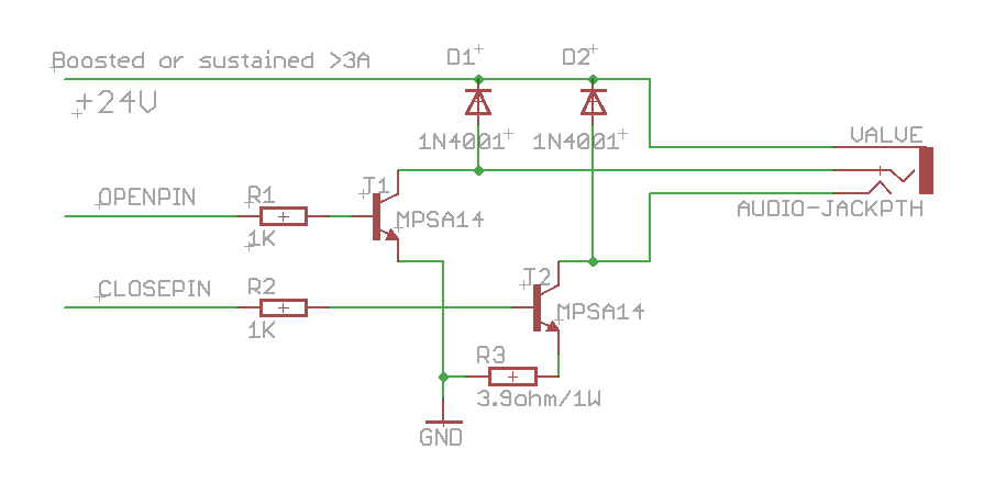
The first thing I want to share about is an update to my previous post that talked about how to control the Orbit 62035 valve. There have been a couple of missing pieces there which I would like to clarify. First, I found that a MOSFET cannot reliably control that valve. I am not sure why, but it may have to do with the on-state drain to source resistance. But using a MPSA14 (NPN darlington) works, and it requires a base current limiting resistor, so I’ve updated the schematic as below. Second, I was reminded that two kickback protecting diodes are needed to protect the transistor from the inductive current from the solenoid, so those are also added. These are the two main changes. The circuit below has been tested to work. Feel feel to leave comments.


Tags:


I was listening to the ‘Ask an Engineer’ show on Saturday night, and they mentioned that the $100 Serbian paper bill has Tesla’s image on it. A friend of mine happened to be traveling in Serbia, and so very luckily, I requested one from him 🙂 It seems this is equivalent to 1.29 US dollars.

And speaking of that, I am excited to post this video I recorded at the Make Faire New York 2010. It’s the ArcAttack guys performing in the middle of a bunch of Tesla coils. Totally awesome!

Tags: ,

After finishing the previous minty water valve controller, I decided to make it an Arduino shield. This way, I can easily stack it onto other shields and extend its capability. I also added a few input buttons, and a DS1337 real-time clock, so that it can keep up with accurate time. Now the circuit has become much smaller, so I can’t produce it with home-made PCB any more(sadly…). Instead, I ordered professionally made PCBs from Laen, and here you are, meet the Arduino WaterValveShield!

PCB board:

Components soldered:

Close-up view:

Connected to a serial LCD display

The schematic:

You can download Eagle schematic and PCB design here. Feel free to use it and/or modify it, but be kind to give me some credit for it 🙂

Parts list with Mouser/Digi-key links: valve_shield_parts.zip 

As for sketch code, refer to my previous posts for code to control the valve and read input buttons. To interface with DS1337 RTC, I use this excellent RTC library.

Next steps:

Tags: ,

At times I feel short of digital pins on the Arduino to handle multiple button inputs. Here is an easy way to use 1 analog pin to handle many input buttons. The way it works is very straightforward: use a resistor network as voltage dividers, and then let each button feed a different voltage to the analog pin. Thus by detecting the voltage we can tell which button has been pressed.

Schematic:

Download the corresponding Arduino sketch code.

As a downside, it cannot handle simultaneous button presses. To do that, one could potentially use resistors at doubly increasing resistance (1K, 2K, 4K, 8K…). Hence by checking the detected voltage, we should be able to tell which buttons are pressed simultaneously.

Tags: , ,

« Newer Posts - Older Posts »