Feed on
Posts
Comments

Note: check out our OpenSprinkler DC-powered version, which uses an innovative circuit design that drives sprinkler solenoids using DC-only voltage.

I often get questions about sprinkler valves, so in this post I will explain the basic electric properties of sprinkler valves. If you are designing a sprinkler controller circuit, understanding these properties can be helpful. It’s a common mistake to assume sprinkler valves work with DC voltage. While most valves indeed CAN be powered by DC voltage (see below), they are designed to work with AC voltage in the range of 22VAC to 28VAC. That’s why if you look at a standard sprinkler transformer, the output is usually AC.

The electric part of a sprinkler valve is the solenoid — it’s a cylindrical-shaped thing screwed into the valve. At the center of the solenoid is a rod supported by a spring. The solenoid has two wires connected to its internal coil. Applying 24VAC on the two wires energizes the coil, and causes the rod to contract into the solenoid. This releases the internal water pressure thus opening the valve, allowing water to flow through the valve. Removing the voltage causes the rod to revert back to its original position. This allows the water pressure to build up internally hence stopping the flow. Because closing the valve relies on internal pressure build-up, it usually takes a few seconds to completely stop the water flow. This also means if your water pressure is too low you may not be able to completely stop the water flow.

IMG_0205IMG_0206

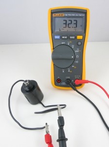
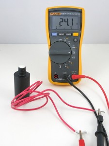
Let’s start by measuring the resistance of the sprinkler solenoid. I have two example solenoids, one made by Orbit and one made by Hunter. According to the multimeter, one measures 32.3 ohm, and the other measures 24.1 ohm. So the resistances are pretty low. If you think about it for a while, you might realize something is not quite right here: if we apply 24V on the solenoid, wouldn’t that produce a 24 V / 24.1 ohm = 1 amp current draw? That’s quite steep. In fact, my sprinkler transformer is only rated 750 mA output current, so it can’t provide enough current to drive even one solenoid?!

The catch is exactly in the fact that sprinkler solenoids are powered by AC voltage. Because the solenoid is made of a coil, it not only has coil resistance but also inductance. When operated on AC power, the inductance produces significant reactance which cannot be ignored. You can read the Wikipage to find out how reactance is calculated, but basically it has to do with the frequency of the input voltage, and the inductance of the coil. Because inductors ‘prevent’ current from changing rapidly, it behaves like a ‘resistor’ under changing current (i.e. AC). The higher the frequency, the higher the ‘resistance’ (i.e. reactance).

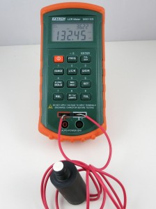
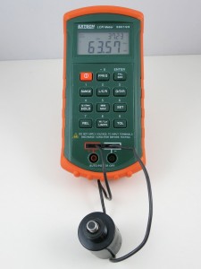
With an LCR meter, I measured the inductance of the two solenoids:
IMG_0207IMG_0209
One reads 63.57 mH, the other 132.45 mH. So if we power the solenoids by 24VAC, 60Hz, which is the standard output of a sprinkler transformer, we will get a reactance of:

This, plus the resistance, gives a total impedance of:

Note that the reactance counts into the imaginary part of the impedance. Using complex numbers is just a convenient way of denoting not only the magnitude but also the phase. For example, when you apply a sinusoid voltage on the inductor, the corresponding current is also a sinusoid wave, but with a different phase. Using complex numbers, the calculation can be carried out quite easily.

Now we can calculate the operating current under 24VAC (rms). We only care about the magnitude, so the current (rms) would be:

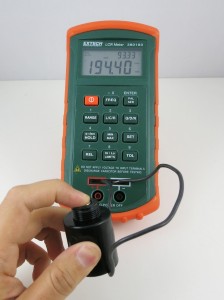
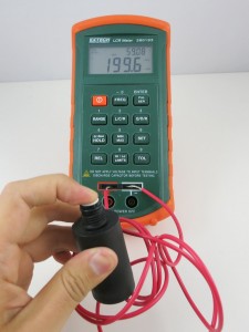
OK, so this is getting closer to the reality. But 0.6 amp current still sounds high. What is missing? Well, remember that when the solenoid is activated, the rod will be attracted into the solenoid, and that can change the inductance significantly. So let’s re-measure the inductance with the rod pushed in:

IMG_0208IMG_0210

Indeed the inductance jumped from 63.57 mH and 132.45 mH previously to 194.4 mH and 199.6 mH respectively. OK, now if we redo the calculations, we will find out that the correct reactance is:

and current (rms) os:

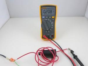
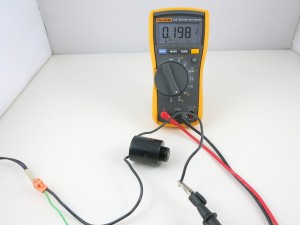
The resulting current is about the same on the Hunter solenoid. So this roughly matches the electric specification of a typical sprinkler valve. It’s actually still a bit off: if we measure the actual AC current flowing through the solenoid:
IMG_0211IMG_0212

The readings are about 0.2 amp. I suspect the difference comes from the measurement of the inductance. On my LCR meter, which can measure inductance at two frequency levels: 120 Hz and 1 kHz, I find that the inductance is measured differently under the two frequencies. Because the actual operating frequency of the solenoid is 60 Hz, and my meter cannot measure 60 Hz, the inductance I am getting is probably somewhat off. That should explain the difference between the calculation and the actual current reading.

The 0.6 amp current we calculated above probably explains the inrush current: when the solenoid is just energized, there is an impulse current that’s typically higher than the holding current. This is because the rod is still out, and hence the reactance is lower, causing a higher current than when the rod is attracted in.

Operating Sprinkler Valves Under DC

Note: check out our OpenSprinkler DC-powered version, which uses an innovative circuit design that drives sprinkler solenoids using DC-only voltage.

From the calculations above, it’s obvious that the coil inductance is important at limiting the operating current when the valve is powered under AC. What about if we power the valve under DC? Obviously we shouldn’t use 24VDC, because that would draw too much current (0.75 to 1 amp). If you search online, you will find plenty of posts talking about powering sprinkler valves using 12VDC. This actually works well in general. Using 12VDC has advantages in that 12VDC power adapters are cheaper and much easier to find; the circuit design is simpler, and you can use the same circuit to interface with other DC devices like relays and motors. In contrast, 24VAC power circuits are more complex and you can’t use the same circuit to directly interface with DC devices.

However, you should be aware that because the sprinkler solenoid’s resistance is pretty low, the operating current under 12VDC will be relatively high, around 400 to 500 mA. This more than doubles the 200 mA operating current (rms) under 24VAC. Also, the coil will heat up more, and this potentially shortens its life. For example, under 12VDC, the Orbit valve above will dissipate 12 * 12 / 32.3 = 4.5 Watt; whereas under 24VAC, the same valve only dissipates 0.2 * 0.2 * 32.3 = 1.3 Watt (note that only the resistive portion dissipate power, inductive portion does’t).

Again, the issue is that under DC there is no reactance, so the coil’s inductance plays no effect at limiting the current. What if we reduce the voltage further to 9VDC, in order to reduce the operating current? After all, the solenoid only needs 200mA holding current to remain activated. Unfortunately that won’t work: I’ve tried powering solenoids with 9V, and I can’t get the valve to reliably energize. The problem is that 9V is not sufficient to provide the required inrush current, so the rod cannot get fully attracted in. However, if the rod is already in, 9V is sufficient to hold the solenoid activated. So if you really want to make it work with 9V, you need a circuit that can provide a high impulse voltage; then once the solenoid is activated, you can lower the voltage to reduce the current (hence power) consumption. A possible solution is to use a boot converter (very much similar to circuits for latching solenoids) to provide an impulse high voltage, but this comes at the cost of increased circuit and software complexity.
148 Responses to “Understanding 24VAC Sprinkler Valves”

  1. Mike Lim says:

    Thanks. Really helpful to know this. I want to dabble more into these toys but afraid I’d be a lifelong student without only equations and no projects under my belt. Glad you are here to somewhat bridge the gap. Have a koi pond and working to keep its waste water from thrown down the drain and instead be used to irrigate the garden. Got my pump requirements figured out and setting out to lay the pipework. Then will I install drip tapes and what not and manually turn them on and off. will then jump into getting your controllers and valves. Guaranteed fun stuff as long as I don’t attempt yet to assemble them together!

    • Bob says:

      This may sound a bit odd but I have a situation where I want the irrigation to turn on when the temperature drops to freezing. While there are lots of products that will shut the system down at freezing temperatures I cannot find a ready-made device that will turn it on. Can I just use regular thermostat that produces 24 volts to control the valve? If not, can you please suggest how this might be accomplished.

      Thank you

      • ray says:

        Yes you can. Most thermostats work with 24VAC system, so all you need is a thermostat, 24VAC power supply, and your sprinkler solenoid.

      • Wayne says:

        Not odd, smart! Water crops to save from freezing. Great idea!

  2. philip says:

    NICE!!
    this information you have given are great for amateurs (with little physic and math background) like me. haha
    keep up the great work my friend. =)

  3. Edgar Collett says:

    Hi Ray,
    Thank you for a very accurate and informative article. I am interested in the use of DC for my 24V AC Orbit sprinkler control valves because of long power failures we have. I want to use a 12V DC backup to drive the coils during power failures. (I was planning to use a DC to DC switching supply, to provide the 24V DC to drive the coil, but your article has put me on the right track). Thanks again, you have saved me the time and effort of experimenting and I now know exactly what I can and cannot do.
    Edgar

    • ray says:

      My suggestion is to apply the boosted 24V DC momentarily to open the valve, once the valve is open, you can keep the voltage quite low (I’ve used 5V and that’s sufficient to keep the solenoid activated). Don’t apply 24V DC persistently as that will burn out the solenoid.

      • Fant says:

        Could you use a 12V DC to 120V AC inverter commonly found for run AC items in a car to just power the sprinkler timer from a bank of batteries? Perhaps look into some of the solar energy to AC parts if a higher quality AC signal is needed.
        Just another thought.

      • ray says:

        You probably can. But as I mentioned in the post, mostly the solenoids will run just fine on 12V DC, so there is no need to convert it to 24V AC.

  4. Andre says:

    I have not tried it, but I am convinced it should work. If you follow ohms law, you could add a resistor in series with the coil to reduce the current. Thus if the coil of the solenoid has a resistance of 32ohms, I would add a resistor of 16 to 32ohms (you will have to try) to limit the current. This will work simply because the coil has an infinitely high resistance until energized. Thus the voltage drop over the coil will be much higher than over the resistor initially (series resistors theory). You will need a high wattage resistor 200mA x says 3V (estimated voltage drop over resistor) is 600mW I would use a 2Watt resistor to make sure it does not eventually burn out, cause a fire or fails. Please note, if you use electricity, the onus is on you to understand, read and ask questions and make things safe. Adding a fuse in series, of 1 or two amp rating will so no harm. Solenoids, transformers and resistors heats up. If you modify circuits (use an AC valve with DC) you should make it safe. Have fun experimenting, reducing current causes less heat!

  5. Mike Berger says:

    Just ran across this info — have a brand new rainbird inline valve that runs at 24vac. Been in electronics all my life so just put a 24 vac control transformer (20va) on it to test it and it chatters bad. (which usually means something needs dc in my mind) BUT, is this typical? Do they NEED water pressure before you apply the 24vac? Never messed with irrigation stuff before.

    • ray says:

      Since AC is 50 to 60 Hz, it’s typical to hear chattering. You can, if you want, power the solenoids by 12V DC, but electrically the valves are designed to work with 24V AC.

  6. james higginbotham says:

    Hi Ray,
    Very informative, but i have the opposite problem. I want to use a standard 24 V AC timer to operate a DC (12 or 9 V? http://www.lowes.com/pd_904-74985-27757_1z0wg76__?productId=3047175&pl=1 valve) since it has hose threads on either side. Is this easily doable?
    thanks – james

    • ray says:

      That’s a latching solenoid valve, you will need an H-bridge circuit to open or close it. This is what OpenSprinkler Bee is designed for:
      http://rayshobby.net/cart/osbeeshield/

      • Chris aplet says:

        I have sucessfully placed a rectifier on the 24 VAC output of the valve to make about 30 VDC a cap would smooth the voltage.

        My question is can I run the timer its self on DC voltage. i want dc voltage output from the station pins. I have been too chicken to hook it up to straight DC voltage to see what would happen. most of the electronics are probably DC any way. I have lots and lots of uses for automation for the timer portion without using the solenoid valves. seem like the big hang up is the valves.

  7. MC says:

    Ray, what a great article on the sprinkler valve/solenoid troubleshooting. I’m rusty on my electronics theory but you provided great examples, explanations and even the formulas. Thank you for taking the time! //MC

  8. BZAG says:

    This implies that the timer simply switches the power to the zone without any further power conditioning, i.e., to test a solenoid (or valve) I can short a zone to the transformer power directly, bypassing the timer, and listening to the water flow. I have a blown fuse in the timer, and a solenoid short (among other possibles) can cause this, but now I can actually test each zone to see if the valve opens up without opening up the valve box. As a precaution, I will use an ammeter between the power source and the zone point to see when the current spikes (so I also don’t burn something else out !).

    If there is something wrong with this logic, I would love to hear about it. Obviously by inserting a new fuse and trying it on the timer, can accomplish the same thing, but based on what the problem actually is, can cause me to blow several fuses and then not really tell me what I want to know, whether it is the solenoid or the timer, for example. But for now, a blown fuse is more indicative of a shorted solenoid than anything else.

  9. Tom says:

    Hi Ray –

    Do you have any understanding of the relationship between water pressure, and required current for activation?

    Thanks,
    Tom

    • ray says:

      I don’t think there is a strong relationship between the water pressure and the required current. Most sprinkler valves require sufficient water pressure to properly turn off / close, otherwise the pressure can’t built up internally to close the water flow. Also the inrush current, which is needed to energize the valve initially, it typically higher than the holding current, but it has nothing to do with water pressure.

  10. Alwyn says:

    Can you use Orbit solenoids on a rainbird controller? They are all new.

    • ray says:

      As long as they are the same type: if the controller is 24VAC controller, then you should use 24VAC solenoids (manufacturer doesn’t matter). If the controller is a latching solenoid controller, you should use latching solenoids.

  11. Alan says:

    Very informative so I thank you for that. I have a problem with a Hunter system and one sector was not working so after checking the wiring and verifying I got 24 V at the valve I presumed the solenoid was faulty and replaced that but the sector still does not work. I notice that when the sector is selected and the solenoid energised the voltage drops off and the valve does not open to allow water. The valve seems fine mechanically as if I open it a 1/4 turn I get water in my sprinklers. Any suggestions? could it be that there is a bad connection somewhere and when load is out on the cable – even the 0.3 Amp when the solenoid operates – this temporarily breaks the connection?

    • ray says:

      When you say the voltage drops off after the solenoid is energized, how much does it drop off? It should still be somewhere around 24V AC. If it’s significantly lower, that means there may be shorting somewhere (likely the wires that go from the controller to the solenoid).

  12. paul says:

    Ray I want to use a rainbird valve on an air compressed cannon to launch bait into the surf
    can I use connectors from a 12 or 6 votl battery? or from the cars lighter.. alligator clips?
    I need the valve to open quick when charged and close after firing

    • Brian says:

      I’ve used 2 9V batteries wired in series for an air cannon with the 24V sprinkler valve. It works ok, However, I’ve found that a manual ball valve works much better, it opens quicker and you get more airflow.

      • Rick says:

        On the ham radio websites (they build air guns to help put wire antennas up in trees), they say that a modifed sprinkler valve has more air flow than a ball valve…

  13. arthur says:

    if for some reason after the transformer ,the feed-in power to the control is read 29.6 instead of 24 ,will the system still be able to run ?

    • ray says:

      Yes, it’s fine. It’s normal to have a no-load voltage much higher than 24. As soon as the circuit starts to draw current, the voltage will drop. Also, solenoid valves typically can withstand higher voltage, at the cost of possibly reduced lifetime.

  14. Stan says:

    I have an older Orbit controller model 57006.Lately when I put the sprinklers on they start when they feel like and also shut off same.Checked power out of transformer 29volts,checked power on each of 5 zone wires leaving controller,looks good.So I figured I must have problem with ground wire since problem exists on all zones.A couple of times when I moved wires by valves(all in one location) it would come on,but not always.While investigating situation i found some sort of cylinder shaped 1″plastic items with three connections,only 2 used,in line with each ground wire from one to the next.My question is what are these things and do I need them or can I eliminate them as a possible source of problems,and just connect ground wire to each valve?

    • ray says:

      It will help if you can post a picture (such as uploading it somewhere and share the link). I don’t think I’ve seen this 1″ plastic items with three connections as you described. It might be part of the transformer, might be something else. A picture would help.

  15. Keith Fleming says:

    Hi
    A different problem too many Solenoids( Hunter) opening on startup. These are on a bowling green so hard to water one green without affecting people playing on other greens
    Cheers
    Keith

  16. jr says:

    Nothing turns on in automatic or when I manually turn on zone 1. I get 28vac from common to zone 1. Im also getting 28vac on all the rest of the zones but I only have zone 1 turned on. If I disconnect the other zones. They no longer have 28vac power on the timer terminals and they have 27vac on the wires for the zones. I tried the timer with tstat wires only to the closest valve and it worked. What is causing my system to back feed the 28vac?

  17. Yair says:

    Hi Ray,

    I didn’t understand why you prefer to make that complicated circuit that makes the high voltage at the beginning (using the capacitor) and then to use the 9v for low current consumption of the valves ,
    instead of using your controller or any oscillator to make DC intervals that can create the frequency you need for low consumption that you get in AC.

    hope you can answer me please
    Yair

    • ray says:

      First of all, this is not a complicated circuit at all:
      http://rayshobby.net/announcing-the-first-dc-powered-opensprinkler-v2-3-dc/
      it just involves a MC34063 as boost converter, and two MOSFET high side switches. Second, converting from DC to AC is a *much* more difficult task, especially if the solenoid draws a fair amount of current from AC. You can’t just turn DC on/off with an oscillator at 60Hz, because the waveform you get would be completely different from the sinusoid waveform of AC. Generating sinusoid waveform from DC is difficult, and being able to supply a large amount of current is even more so.

  18. VicW says:

    Following this thread and not being smart in the relationships for electrical circuits, I am trying to figure out if a Madison M8000 float switch inserted between one wire of a sprinkler solenoid will handle the voltage (13.9 on Multi) and the amperage (.2)amps.
    The specs on the float switch:
    Max Switching Voltage : 220V DC/AC;Max Switching Current : 1.5A;Max Breakdown Voltage : 300V DC/AC;Max Carry Current : 3A
    Max Contact Resistance : 100m ohm

    So with my limited understanding, it looks like the switch will work and not burn out if I simply insert it between the solenoid and the controller via the common wire.
    I’ve ordered three ( In case they burn out in my testing) to try and rig an auto fill system for my pond. The idea is the controller timer will command power to the solenoid 6 times a day. If the float switch is up (water level acceptable) then the circuit remains open (via the float switch) and the valve does not open. If the float is low, the circuit would be closed and the valve will open for the programmed time.
    Why do it like this? My pond can handle city water input in small amounts and this will avoid killing fish due to continuous influx of city water in case a float switch fails. The auto top off is a convenience for me vs. the need to make sure the pond is always at a given level.
    Anyway, you think the float switch with specs like described above will work to complete a solenoid valve circuit? Sprinkler timer is a standard Orbit timer system. (24V AC)

  19. Zeke says:

    Hi Ray
    I want to connect a AC-DC adaptor to a motion detector security light socket to operate an electric sprinkler valve. I want to scare away deer from my garden.
    The adaptor input is 120V-60Hz
    The output is DC 22V 500mA 11 OVA
    I’ve read the earlier replies, and understand there is a burn out problem.
    Will this setup work?

    Thanks,
    Zeke

    • ray says:

      If your sprinkler valve is a standard 24V AC valve, you should use either a 24V AC adapter, or 12V DC adapter. 22V DC is too high. If you choose the 24V AC adapter, then as you said you need a AC-DC converter if you intend to power the motion detector from the same power source. On the other hand, if you choose 12V DC for your valve, you can use a simply linear regulator like 7805.

      Of course if you don’t mind using two separate power adapters, you can always use a 5VDC power adapter for your circuit, and 24VAC for the valve.

    • Waldo Juarez says:

      Hi Zeke. I was wondering if you ever got this to work? (I know I am coming 8 years late to the party) I have successfully made a system like this and would be happy to guide you through some of the difficulties (and there are quite a few).
      Waldo

  20. Amin says:

    Hi Ray

    Thanks for the great explanation. I already have a rasberry pi with a few relay switches that i’ve used to control stuff like garage door opener etc. I also have an existing electronic irrigation controller that’s pretty basic (really old). However, it has a button to manually start the sprinklers. I’m thinking of setting up the circuit in a way that i can control that button press with my relay. That way i can effectively control irrigation circuit with the PI.
    Any suggestions on things to watch out for?

    Thanks
    Amin

  21. Anthony says:

    I enjoyed the above article, it gets down to the nitty gritty of DC voltages. I am using a 15volt AC 300Mah xformer with an unloaded voltage of 17V AC. It runs system great no problems engaging orbit and rainbird solenoids, the orbit is 100′ away using 22gau wire on top of it. I like this Xformer as it very efficient and has less than a watt resting current and not a IV class either. I am probably a volt or 2 away from these solenoids not working, but all has been well for years. Thought you may find it interesting…I wonder if putting in a class V 12v 1 amp DC would be as good, resting current should be better, but ultimately higher operating current. BTW 1 watt 24/7 at 10cents kwh is about 1 dollar per year.

    Thx

    • ray says:

      I’ve read online that 12V DC is generally sufficient to drive typical 24V AC sprinkler valves. Technically, 12V is a bit on the low side for providing the impulse current, and a bit on the high side for providing holding current. That’s why the circuit in OpenSprinkler DC uses a booster to boost the voltage up to 24V, providing sufficient impulse current, then disables the booster and drops the voltage to 9V to provide holding current.

  22. Anthony says:

    Additional question I have a water master 4 zone timer, I don’t think I can put DC in. It does say AC in, it obviously converts to DC for timer. What your experience doing that? Thx

    • ray says:

      This completely depends on how the circuit is designed. Generally, the circuit itself can be powered with 12V DC no problem. However, most sprinkler controllers (including OpenSprinkler AC version) uses triac to switch solenoids. Triacs can only switch AC current and not DC current. Specifically, it can turn on the DC current but will not be able to turn it off. This is because triac turns off at the zero-crossings of the AC current. DC does not have zero-crossings, so it can’t turn off. As a result, you most likely have to replace the triacs with DC transistors or MOSFETs in order to use DC voltage and still be able to switch the valves.

  23. Ed Wehking says:

    Is 24 VAC strong enough that I should be shocked when touching the wires connecting to the solenoid wires? I am trouble shooting a problem and do not have a Voltage or ohm meter…

    • ray says:

      You might sense a numb feeling on your fingers but it’s very subtle and it’s only when you touch both wires at the same time. 24VAC is considered low-voltage. However, since it’s AC, the peak voltage can momentarily go beyond 36V which is considered the safe voltage.

  24. Steve Lawson says:

    I have a case where I want to operate a sprinkler valve in a remote location where running a powerline would be difficult. So, my solution is to use a solar panel. Originally, I was designing a PWM DC to AC converter using a MOSFET H-Bridge. But, halfway into the design the thought came to me: “Is it really necessary to use AC?” A Googling brought me here.

    Faced with the ambiguous answer, I had a flash: A solar panel of the correct configuration, might be able to supply the startup current and yet rollback for the holding current. I selected a Monocrystalline silicon solar panel [from Electronic Goldmine] with the following specs: Vmp 18V, Imp 190ma, Voc 20.7V, Isc 210ma, Pmax 3.5W. I tried it today at high noon. It quickly opened the value and held at 240ma!

    I plan to use a PIC MCU to control the value and also monitor the voltage on the panel. The only battery needed will be a 3V backup battery to keep the MCU running when there is no power from the Solar Panel — the MCU will sleep most of the time, waking only to test the solar panel for power. I might even be able to use a SuperCap instead of a battery, depending on how low I can get the standby current — and with the latest uWatt PICs I can get it pretty low!

    I live in So. UTAH so not much concern about cloudy days 😉

    • ray says:

      If your solar panel can output at least 5V, or even 12V, you can use the OpenSprinkler DC or a similar circuitry to operate sprinkler valves. Basically OpenSprinkler DC has a boost converter that bumps the input voltage to 24V momentarily to energize the valve, then drops it to input voltage (5V to 12V) to provide holding current.

    • Steve Lawson says:

      Well, I did it! I programmed a PIC to wait 2 hours, then turn on a sprinkler valve for 15 minutes, then wait 2 hours, then… It’s all powered by a single solar panel — the PIC and the valve solenoid, both. It works great under full sun. The solenoid pulls in with gusto and it doesn’t even get warm, and it’s very quiet. On the rare cloudy day, the garden can go without water 😉

      I’ve had it running for about a week.

    • Steve Lawson says:

      Well, the valve failed. It now has intermittent action and often sticks open! Not sure if running it with DC current is what caused it to fail. I designed a circuit that uses Pulse Width Modulation [PWM] to convert the DC from the solar panel to a fairly clean AC signwave (24 steps @ 31kHz, filtered with a hefty dual 18mH inductor) with enough power to drive the value. The valve hums slightly the way it does with 24VAC from a mains connection.

      I bought a new valve and so far, it works great.

      • ray says:

        Actually most 24VAC valves work just fine with DC voltage — on various forums people have reported using 12VDC directly to drive 24VAC valves, and it works fine. Technically 12VDC is a bit on the high side to provide holding current. The circuit I designed for OpenSprinkler DC is better in that it generates a high impulse voltage to energize the valve, then lowers it to input voltage (about 7.5 to 9VDC) to provide holding current:
        http://rayshobby.net/announcing-the-first-dc-powered-opensprinkler-v2-3-dc/

      • Steve Lawson says:

        Maybe the voltage from the Solar Panel was too high. Under noon summer sun it can get up to 18VDC or more (20VOC). That might have overheated the solenoid. But, the Short Circuit current (from the Solar Panel) is only 210mA and the solenoid holding current is 230mA, so it seems unlikely. I would have to throw it on the scope to tell for sure, but the Scope is inside and the Sun is outside (don’t really want to take my expensive scope out into the yard 😉 )

        Based on what you’re saying, it sounds like the valve failure was coincidence.

  25. Christopher says:

    Hi Ray,
    You are current on your electricity!

    I am planning to use the RainMachine (24V AC with max 600mA) to operate a couple of sprinkler valves.
    But also, I want it to trigger a 24V DC 350mA lock (a quick opening of a latch to release the content of a feeding box, so the current is just to trigger, not to keep open). The RainMachine guys say it would work.
    Do you have an opinion?

    Also, I can not find anywhere the answer to: how far from the RainMachine panel can a valve be? In other words, how long can the cable be and still operate properly?

    Thanks in advance for any input.
    Best,
    Christopher

    • ray says:

      Generally that depends on the resistance on the wire. For longer distance, you probably want to use thicker wires.

    • Steve Lawson says:

      I might be too late with this answer, but in case anybody else is Googled here (did I coin that verb form?):

      Use a wire table (like this one: https://en.wikipedia.org/wiki/American_wire_gauge) and do the following math to figure out the voltage drop in the wire. Usually, if you hunt through the enclosed documentation, you can find the minimum voltage the valve is spec’ed to run at. For instance, the Orbit valve I purchased can run at a minimum of 18VAC. So, for a 24VAC source (i.e. the transformer or the switched voltage from the box), we can lose:
      24 – 18 = 6V
      and still be OK. If you know the wire gauge of the wire you’re using, look up the Resistance/Length on the wire table. Lets say I’m planning to use 20 gauge wire. From the table referred to, above, 20 AWG wire is 10.15 milli-ohms/foot (m?/ft) — the same as ohms/1000 feet (?/kft). And, lets say the sprinkler valve is 1000′ away:
      1000m?/ft * 10.15? = 10,150m? = 10.2? (rounded it off because two decimal places is just too fussy for reality, in this case)
      Because there are two wires going to the valve, the “round trip” distance is actually 2000′, so double the resistance:
      10.2? * 2 = 20.4?
      Also on the enclosed documentation should be the “inrush current” — for my valve it’s .35 Amps (or 350 mA). Ohms law states that:
      Voltage = Current * Resistance (or E=IR)
      So,
      350mA * 20.4? = 7,140 mV = 7.1 volts
      Which is more than 6 volts, so we need bigger wire. How about we try 18 gauge, which is 6.385?/kft:
      2000 * 6.385 = 12.77?
      .35A * 12.77? = 4.3 volts
      Much better!

      And, wadaya know. The documentation recommends 18 gauge for runs less than 800ft, else 20 gauge.

      I did a little “hand waving”, there, so here’s the behind-the-scenes:
      350mA is the same as .35A, because ‘m’ or ‘milli’ means one-thousandth. And, 350mA/1000 = .35A — same thing for the 20,400m? to 20.4? conversion and the 7100mV to 7.1V.
      In the 18 gauge calculation, I doubled the distance for 2000′, instead of doubling the resistance, later — same difference.
      Wire has resistance, and when current flows through wire, voltage is “dropped” across the wire because of that resistance. For short wires, that resistance is usually negligible. But for long wires, that voltage can be significant. “Ohm’s law” is a formula for determining that voltage drop (ohm’s law is, technically, only meant for DC, but, because there is no significant inductance or capacitance in the wires between the source and the valve coil, it works out the same as a DC circuit)

  26. Rayray says:

    Hi Ray,

    Can we use 24 VAC controller to turn on DC latching solenoids?

    Thanks,

    Rayray

  27. Scott says:

    You seem very knowledgeable. Question: I had three stations running off a valve and head toro system. ie…like a golf course or a large park. Manual function was fine. Comm didn’t work. I replaced all three solenoids. Still nothing. I traced the power and the comm. All seemed good. I always got 24 v when solenoids were not attached and the com seemed fine. When I attached the solenoids I lost all power. Out of last resort I replaced all solenoids again. It worked. Are not all 24vac solenoids the same for all valve and head for Dt50’s? I have no idea how I solved this problem?

    • ray says:

      You should find out if the solenoid is 24VAC type. Generally 24VAC solenoids have a resistance between 22 to 50 ohm. If the resistance is much lower, it’s most likely a latching solenoid and it cannot be used with 24VAC controller.

  28. David says:

    I have a small nursery with 9 24V AC Orbit valves and a controller that must be wired thru a GFCI outlet. The breaker can and has been unwittingly tripped, cutting off the controller, which kills baby plants. I found Hunter makes a hybrid controller with a solar panel option that will continue running if cut off, but it operates DC valves.

    Is there a way to make the two work together? I’m told the valves open but then close again immediately, which is holding voltage I gather here. If not should I try Hunter DC solenoids on Orbit AC valves – or is that a silly idea? Last idea, does Orbit make a DC solenoid for their AC valves that works with Hunter controllers? Otherwise it’s 9 new valves… thanks!

    • ray says:

      I really don’t know. DC solenoids have two types: latching and non-latching. You need to find out which type it is, and what type of solenoid the controller can handle. Many DC solenoids I’ve seen are latching type, and are typically used in battery-powered controllers due to their power efficiency.

  29. Keith says:

    I have a similar question to David’s. I have Orbit valves which I assume are AC valves as the controller is plugged in and I don’t see a transformer. (Is there an easy way to know for sure?) I have new puppies that dig up the cable, so I want to get the Hunter battery operated controller that I can place right by the valves (all four are together.) Since it requires DC valves, can I replace the AC valves with DC without having to buy all new valves and replumb them?

    • ray says:

      Most AC solenoids have resistance between 22 to 50 ohm. So simply testing the resistance should allow you to tell. DC latching solenoids have resistance generally below 10 ohm.

  30. Jarred says:

    Hi there,
    So I’m sitting with the current situation and hope someone can help answer me… this will be my best explanation!

    I have a 12VDC power supply going to 2 X 12VDC Latching solenoids (attached to water valves) …

    POSITIVE polarity opens the valve and NEGATIVE polarity closes the valve. Works great

    This is the issue,
    I now want to open one valve and at the same time on the same circuit, close the other valve. So a simultaneous switch…
    Its a water pipe that splits to 2 pipe lines, both pipe lines cannot be open at the same time as the water pressure drops so one pipe needs to close while the other pipeline opens… so there must be a constant flow of water.

    The one solenoid valve is wired positive, and the other solenoid is wired in reverse.

    How come is it that one solenoid will close, but the other wont open when i provide a 1sec pulse of power (the solenoid that is suppose to open only opens for the 1sec pulse of power i provide, remember these are latching solenoids)

    if I provide power separately to each solenoid then it works hundred percent?
    Is it shorting and only letting the one open? How can I get this to work?
    Should I place a diode in line?

    Hope this makes sense and someone can help me!

    • Jarred says:

      Just tried a diode… Won’t work because of when I reverse the polarity… Gosh…

      Also another note to make you aware of is that both solenoid are DC but the one is a Rain Spa and the other is a Hunter. Nothing specified on what volts it’s at but the rain says 30vdc or less and the hunter I think is 9VDC… Both work fine on their own with 12VDC

    • ray says:

      Generally you need an H-bridge to operate each solenoid. That way you can independently control each solenoid. Take a look at the OpenSprinkler Bee circuit:
      http://rayshobby.net/cart/osbeeshield/

  31. Tamilarasan says:

    Sir , my doubt our system are installed 120 v -24 v transformer but in the field we are checked cable 32 or 36 voltage next some time solenoid coil we seen on top crack and function afterwards change coil it is working , what is reason for coil crack on top.

  32. Adam says:

    A tree in our yard was recently hit by lightning. The next day, I discovered our irrigation system wasn’t working and I was unable to turn on the controller. I started the troubleshooting process and found I needed to replace the transformer (AC wall adapter). With power to the controller, the system still didn’t operate correctly (two zones came on at the same time and the module for zones 1-4 started smoking!). So, I started troubleshooting again and was advised to test the resistance to each zone. However, the ohm meter produces a wildly fluctuating reading for every zone (there are 12 total) in the system. There isn’t a single zone that has a steady reading. Any ideas? My fear is that the lightning affected the common wire and I’ll have to spend either a significant amount of time, or a significant amount of money to find exactly where the problem is.

    • ray says:

      If the circuit is damaged by lightning, it’s possible that the triacs are damaged resulting in them losing control from the microcontroller. To avoid the circuit affecting the measurement you should remove the wires from the controller and test resistance again.

  33. Tim says:

    Hey. I have an issue where a zone isn’t working.. so I am trying to replace the valve. The System is a Hunter.. a Hunter controller and Hunter valves (24vac). I replaced the valve with an orbit (24vac) but it doesn’t work. I successfully test at 24 volts when energized. I’m not sure why the valve isn’t opening.

  34. Nick says:

    I am interested in using a sprinkler valve to control output to a pool slide. Right now we have to screw a hose into our outlet in the pool and my wife and kids have a hard time getting it in there. My idea was to throw a sprinkler valve in the discharge line so I could just put a switch poolside. Problem I am seeing is that most sprinkler valves are normally closed. I could run a normally closed but it would be energized more then it would be off and I worry about life expectancy. They do make normally open valves but they are a lot more expensive. Is it ok to run a NC valve open 95% of the time?

    • ray says:

      I think it’s fine. Other than it would increase your electricity bill slightly, I don’t think there is any problem running it open most of the time.

  35. mark says:

    Hi, I was replacing 3 valves , when it came to wiring it was mess in place.
    There is a bundle of smaller wires, one thick white wire and one thick red wire.
    The white looks like a common return, but it looks like one of the thin wires is also
    connected. The thick wire is also connected at least to one. Is the red to tie to the voltage
    to something fixed . When I cut the red, and white, none of the other 4 stations
    didnt work either. Any ideas ? What should I check ?
    Thanks Mark

    • Joe says:

      Your best chance is to take a look at the controller side and see what colors you got wired to zones and commons. If you have a multimeter you can figure out which wire goes where, even if the colors in the controller box differ from those of the valve box.
      The thick wires will most likely be commons, while the others will be the independent zones. Many controllers have multiple common wire outputs, maybe the guy who set up the system simply put different colors for the different commons in order to split the current in two. I don’t know how many valves you have in total, but I suspect half of them were running with the thick red as common, while the other with the thick white as common.
      I always take photos before I split cables or harnesses, just in case.

  36. Michael says:

    Thanks for the info. I have a question hoping you can help. I have a hunter system powered by 24v. I was having a problem burning out solenoids every couple weeks. I had new wire run last year, didn’t have a problem last year after I ran it. But when I started the system up after winter a few didn’t work. I replaced them and a few weeks went by and I have 4 more that need to be replaced. I get a voltage reading around 13v when I check the voltage at the solenoid. Thanks for your help.

    • ray says:

      I would suggest checking the resistance of the solenoid. It should be between 22ohm to 50ohm. If it’s too low, that means the solenoid has a shorting somewhere and should be replaced.

  37. Rick says:

    Hi,
    Very interesting article. Instead of boost circuit, would it be possible to use pwm arduino output and vary the duty cycle after a few seconds ?

    • ray says:

      It may be possible. In that case, the power circuit can provide a stable high voltage (like 24VDC) and the microcontroller uses PWM to reduce the effective voltage after the valve is energized. I have never tried this before and it’s worth investigating. The main technical challenge is that this requires PWM output per zone, and Arduino doesn’t have that many pins that provide PWM output.

  38. Barry says:

    The 500mA 24 VAC power supply I bought from OpenSprinkler last month tries to open the valves, but can’t quite. I have Orbit valves, and I’m swinging by Home Depot to buy their power supply, rated at 750mA. Do you ever get this failure? I was thinking about getting a capacitor to see if that’d help first, but local ones are smaller than what I was hoping to use. Thoughts?

    • ray says:

      Hi Barry, 500mA should be able to power at least a couple of valves simultaneously. If you have a multimeter, check the resistance on the two wires of the solenoid. It should be between 22 to 50ohm. If it’s too low, that means your solenoid is shorted somewhere and that could explain why the adapter can’t power the valve.

      Also, just to make sure, your Orbit valve is rated 24VAC, right? Orbit also makes latching solenoid valves that should never be powered by AC adapter.

      • Barry says:

        It’s definitely 24VAC. I have a spare valve, and on my workbench, I can FEEL it latch for a second, then drop out. I’m going to call Orbit and dig some more, but I’ve now got a lot of $ wrapped up in grass seed, and if I don’t get it fixed, I’m going to have to buy an Orbit controller.

      • Barry says:

        I figured the $80-ish Orbit 12 zone controller wouldn’t be too expensive to try, so I did. It worked. I’d still like to replace it with OSPi, but maybe when I get a chance, I’ll take it apart and see what they used for relays on their board, and compare specs.

      • ray says:

        Sprinkler controllers almost universally use triacs and not relays to switch solenoids. Relays certainly would work just fine, but they are more bulky, expensive, and slow to switch.

  39. Pete says:

    I have a Leit 2 solar controller that seems to have died but the nerd in me wants to know for sure. It uses latching relays which can be tested by momentarily connecting them to a 9V battery, reversing the polarity will close the valves. I tested the solenoids this way and can switch the valves on and off with no problem. Placing a multimeter in DCV mode across the controller wires i can see a momentary voltage spike but it doesn’t catch the peak voltage. Do I need a oscilloscope to capture the peak voltage and perhaps current too? I would expect to see 9 volts peak, do i need to worry about the current? I would assume if the voltage is low the current would be low too… and of course do you know how low the voltage can go and still work latching solenoids?

  40. Joe Godinez says:

    I am getting 28VAC going in to the timmer, but the solenoid valves are not turning ON; Furthermore, I am getting the No AC voltage display on the timmer screen. Please help

  41. Sal Magaña Jr says:

    Hi so me and my coworkers have been doing some retrofitting. We’re working with Superior Brass Inlet valves and they all use a standard 24V solenoid. Long story short the main clock is no longer working so we’ve been installing portable Hunter Node’s the single station series. Normally they are used on a latching DC solenoid on those plastic hunter valves. We’ve butting cutting off the latching solenoid and attaching it to the Superior 24v solenoids. To get the node to work we used round magnets either on top or under the solenoid, were still experimenting since were using diff types of magnets, double sided and different pull lbs. Rather than dig out and replumb and replace the Superior valves with those Plastic hunter ones, the magnet retrofit has worked for the most part. Is there a better way to get the Nodes to work with the Superior solenoids, I know it’s a DC node trying to power an AC solenoid, is there a special solenoid or different portable clock out there or is the Magnet trick the way to go. Any info is appreciated.
    Thank You

    • ray says:

      I am not sure. I’ve seen that Orbit makes valves that accept both DC latching and 24VAC solenoids. So if one solenoid goes bad, you can get either DC latching or 24VAC solenoids to replace it. I would assume Hunter’s solenoid design also provides this flexibility, but if you are trying to fit a solenoid of a different brand, that’s a totally different story.

      • Sal says:

        Hi thanks for the feedback, we were using the same solenoids from the Superior valves and retrofitting them to work with the hunter nodes. I ended up finding these universal DC solenoids! that fit on the Superior valves and come with their own magnet and work with the hunter nodes.

  42. Fred says:

    Hi Ray:
    Thanks for all your valuable advice.
    I’ve recently had a drip system installed as part of a Hunter total 4-valve system used to irrigate my lawn and plants. The problem I have is that the external drip valve vibrates when on, and it transmits the vibrations to the pipes inside the house and it gets quite noisy. The valve is a new brass Champion 24VAC. While checking the voltage at the controller, I found that the input voltage is 34V (no-load) and when turned on, the voltage drops to 32.5V and each station while running gets about 31V. Could this be causing the rattling of the drip system? The other valves are noisy but do not vibrate as the new one. Is the higher voltage the problem or is there anything else that you can think of?

    Thanks so much

  43. Paul S. says:

    Hi Ray.
    I’m trying to use a sprinkler control valve to shut off a cold water supply pipe in the event of a 120V AC power outage (to avoid possible overflow of an AC powered bathroom drainage pump system).
    As it needs to remain on indefinitely (except during power failures), I’d like to minimize power usage — perhaps by using DC low voltage (~9v?) with a DC latching type solenoid. But as it’s a permanent installation, I want to power it from the 120V circuit to avoid need for battery changes.
    Is there a simple, inexpensive set up you could recommend to do this?
    Thanks for any suggestions.
    Paul S.

  44. Baz says:

    Awesome article, precisely the info I was looking for and the only place I could find it!

  45. David says:

    I have a solenoid that makes a clicking sound approximately once every second. I have proper voltage at the controller on the zone terminal. I can also measure approximately 26 volts at the valve when the solenoid wires are disconnected but once I connect the solenoid it starts clicking and voltage fluctuates too quick to measure. The solenoid coil checked out ok good but I tried a new just to be sure and I still have the same problem.

    • ray says:

      Try another solenoid and see if it’s the same symptom.

      • David says:

        That was one of the first things I tried. I even tried that again after cutting the original wire nuts out and making new connections. Still had the same results

  46. José Chiluisa says:

    Buenos días, mi pregunta es acerca de la activación de los solenoides hunter de 24VAC, yo quiero activar los solenoides con un transformador directamente para hacer unas pruebas pero cuando conecto el transformador de 120VAC a 24VAC al solenoide hunter este empieza a activarse y desactivarse rapidamente hasta q quito la alimentación y si le coloco un puente de diodos ahi si funciona normalmente, porque ocurre esto si la valvula es VAC, Gracias por la respuesta

  47. Paul says:

    Hi Ray,

    Interesting article!
    I am struggling with my watering system. 5 zones with 5 rainbird dv-100 valves(24vac).
    The original rainbird computer died and i would like to change the setup to work with my Fibaro Home Center (z-wave domotica).
    One component fibaro offers is a RGBW controller which can work with 12-24 volt (dc only).
    I would like to use this to control the valves which means i need to switch to a 12vdc powersupply. Din rail)

    Would any 12 vdc power supply be ok? Any requirement on Ampere and wattage? Maybe a stupid question but i am not familiar with electronics..

    Thanks,

    Paul

    • ray says:

      12VDC is fine: technically it’s a bit high for providing the holding current required by sprinkler solenoids. That can potentially shorten the lifespan of the solenoids, but there hasn’t been any principled study about this. The OpenSprinikler DC-powered version uses an innovative circuit design that drives sprinkler solenoids with DC-only voltage. It solves the problem of solenoids requiring high impulse current vs. low holding current, but using a boost converter internally to generate high impulse voltage and lowering it to input voltage to provide holding current.

  48. Cav says:

    Ray,
    Nice article! Searching the webs I see a few people asking the same question I have and not finding answers. The question brought me to your article. Can I run multiple zones at once? Currently I balance all my zone loads to match my pump. I have a drip zone that causes the pump to cycle too frequently so I tie it to one of the other zones successfully running 2 valves with my orbit timer. However, this limits my run time options for the drip zone. I would like to run it longer than my other zones. Is there a relay or chip I can tie in to multiple zones that would isolate them from each other and trigger the drip zone? (Example, zone 1, 2, 3 would also trigger drip zone)
    Hopefully not too outlandish of a question.
    Thanks!
    Cav

    • ray says:

      You can run multiple zones at the same time: it depends on the output current of the transformer. If the current rating is low, the transformer may not be able to supply enough current to keep many valves on at the same time.

  49. Garrett says:

    Hello Ray,
    I have an Intermatic T8845PV timer that runs off 120VAC with a transformer that should put out 24VAC going to a solenoid that runs off 24VAC as well. My problem is that when I checked the power coming out of the transformer I’m getting 29.3VAC. Will that be too much voltage to the solenoid and eventually burn it up, or is that okay seeing as there’s no load on it? Once it sends power to the solenoid will the voltage drop? Thanks in advance.

    • ray says:

      It should be ok: AC transformers are not regulated so typically output higher voltage when there is no load. As soon as circuit or solenoid draws current from it, the voltage will drop to 24 to 26 volt range.

  50. Patrick says:

    I want to use a 24vac transformer and a switch to control 2 sprinkler valves (separate switch for each valve) to turn a misting system on and off. Would you recommend adding a fuse? If so how many amps? (1?)

    Thanks

  51. Jim C. says:

    I have an ancient irrigation system,@1980. Each of the four zones is activated by a switch, same as one would use to turn on/off an overhead light. To the best of my knowledge there is no transformer in the system. Is it possible that the old solenoids operate off normal house current. If that is the case, then I assume replacing a bad valve with a Rain Bird CP100 (24VAC) would be an exercise in futility. Any thoughts?

    • NeoGeo says:

      (carefully) check the voltage at the solenoid itself and replace with appropriate unit.

      (I can’t imagine they used mains voltages at a solenoid valve for water but crazier things have happened…)

  52. José Chiluisa says:

    Good morning, my QUESTION IS About 24 VAC Hunter Solenoid Activation, I want to Activate Solenoids With A Transformer Directly For Testing, But WHEN I connect the transformer to the 24 VAC Hunter Solenoid, it starts to Turn On and Off Quickly Until I remove the Power, then I put a bridge of diodes and function normally, why does this happen if the valve is VAC?
    Thanks for the reply

  53. Jim S says:

    Hi Ray,
    great articles and tips.. I’ve a challenge for you.. I want to replace this:

    https://www.amazon.com/Intermatic-T104-208-277-Volt-Mechanical-Switch/dp/B000BQOX88/ref=sr_1_4?ie=UTF8&qid=1499791214&sr=8-4&keywords=pool+timer
    with a DPST high capacity relay that can switch about 30 to 40 amps at 220vac (as this Pool timer does) but instead, control the relay’s coil from my smartphone with a zone control output lead ( and common) pair from this:

    https://www.amazon.com/Orbit-57946-6-Station-Sprinkler-Controller/dp/B01D15HOIQ/ref=sr_1_1?ie=UTF8&qid=1499791377&sr=8-1&keywords=orbit+wifi+water+timer

    I am worried that since the relay is switching 240VAC at 30 amps and fairly pricey, that I really need a relay with a compatible RELAY coil specification that is similar to the Orbit AC relay in your write up above) .. can you point me to a High current capacity relay compatible with this application? I think the Swimming pool motor I am trying to control from the Orbit H-hyve smart Timer app is 1.5 HP at 220vac.

  54. Scott says:

    Station 2 wouldnt work. When i pulled wire out of station 2 on timer and attached to number one station the zone came on and the timer started to smoke then zone turned off. Possible faulty solenoid?

    • ray says:

      Probably shorted solenoid. You can measure the resistance on the two wires of the solenoid, typical 24VAC solenoids have resistance value about 20 to 50 ohm.

  55. […] didn’t pay attention to whether it was DC or AC – I just assumed they were the same. I found a blog post that provided a very good explanation on the differences. 24 volts DC works, but it draws way too […]

  56. David Kim says:

    Thank you, Ray! I’ve been enjoying your articles.
    Looking to put in a drip control system and have been researching open/hack/DIY options. Yours looks exceptionally good!
    Cheers,
    David K.
    near Seattle

  57. Dan says:

    Hi Ray,

    Just received my OpenSprinkler bee and I have it hooked up to an existing system which used 24vac output voltage. Everything is working fine except when I activate a zone I can hear the solenoid lift momentarily but the valve does not stay open. Seems like it needs more current to keep the valve open. Any tips?

    • ray says:

      Make sure you use sufficiently thick wires as the wire resistance can be significant in limiting the current flow. If it’s still not solved, you can go to opensprinkler.com and open a support ticket.

  58. Carsten Goellner says:

    While reading your very informative article I had an idea to enhance 12V DC usage in combination with 24V AC valves.
    Why not simply use a resistor with 27 Ohm in series and parallel to this resistor a 1000 uF 16V capacity (electrolytic capacitor). This will allow to give the valve the right high energy impulse at the beginning, but reduces afterwards once the capacity gets loaded the voltage to U/2.
    I just tested my idea and it looks to work fine.
    With greetings from Germany, Berlin,
    Carsten

    • ray says:

      Well, I would think the resistor is going to dissipate power and that’s less ideal than using a resistor-less solution.

  59. John Aylmer says:

    When I have power and moisture together I am mindful of corrosion. Moisture and DC may result in electrolysis corrosion, using AC instead corrodes for one half cycle and restores it on the other polarity swing. If the AC is perfectly balanced then there should be no corrosion unlike using DC.
    Keep it dry but that’s hard to do in this environment year after year.

    • ray says:

      Are you referring to soil moisture sensor? Here there is no exposed wire or lead, so I don’t see how corrosion matters.

  60. lopic says:

    Hi,
    I try to use a 24VAC RainBird Valve (model 100-HV-MM), so, the first step is to try it with 24VAC, but I am surprise about the noise of the valve when it is powered.
    The resistance value about 80 ohm, current is 0.2A (@30VAC).
    The “real” voltage is 30VAC, but it is the same with 24VAC (real 24VAC).
    The sheme is simple : 240VAC to 30VAC (10VA transformer) 30VAC connected to the valve.
    (I will add a timer on primary as soon as this check status will be OK)
    I have also tried it with 12VDC and the valve top move from a few millimeters, and it seems that’s works (but without the horrible sound of the 24VAC)
    For the moment, I don’t have pipe and water pressure to make a real conditions test.
    I want to powered with 24VAC in order to use my valve for a long time and the solenoid is made for VAC voltage (and I have read comments in this (very useful page).
    All should be simple but something looks strange, what’s wrong in my simple use case ?
    Lopic

    • ray says:

      AC is indeed noisy, so that’s expected. If the coil resistance measures 80ohm, 12V is slightly on the low side, you can go up to 15V, to provide 0.2A holding current.

      • lopic says:

        Thank you for replying, but in my case, I use 30AC, it works, but do you think the noise when valve is operated is OK, or it could be a problem for a long-term use ?
        As you said, “electrically the valves are designed to work with 24V AC”.

      • ray says:

        Yes, 30VAC is fine — these valves are designed to handle a pretty wide range of voltages. Also, AC adapters are un-regulated, so if you measure 30VAC without load, it will probably drop to close to 24VAC when the valve is actually drawing current from it.

  61. Eli Ednie says:

    This looks like the place I should ask why does my Galcon DC 6S (2×9V) cyclic mist timer only work at minimum 12 seconds on DC latching solenoids when it is set for any seconds less : 1 second = 12 seconds / 5 seconds = 12 seconds, etc? Residual magnetism ?
    It does longer durations than 12 seconds fine at any cycle,
    But I’m using it at an off grid mist propagation facility for fruit tree cuttings.
    I tried an AC non-latching(?) solenoid & it clicks on / off for about 1 – 5 seconds & I can make that work, but have to do a trick to double the cycles ’cause it’s only turning on with DC on / off signals
    So 1 second every 2½ minutes would do, or 5 seconds every 3 or 5 minutes, but it’s not a reliable hack.
    The unit is supposed to do 1, 2 ,3 ,4, 5… or any seconds per any minutes during the daylight operational window.
    Are there DC non-latching solenoids I should be looking for ?
    Are DC systems not designed for intermittent mist ?
    My AC one works fine at home on AC solenoids.

  62. Jay says:

    I’m trying to figure out problems in my 20-zone system. I think the controller is dead. Can I use a 24v ac transformer to directly connect to the common wire and the wire to specific zone to determine if the zone’s solenoid works properly? I have disconnected all zone wires from the non-working controller and now have access to the individual wires to each solenoid.

    • ray says:

      Yes you can connect 24VAC between COM and any individual zone wire, and that zone should turn on, if the zone solenoid is good.

  63. Isabel Marron says:

    question: I have a 110 output sprinkler timer, with a bucknor/superior 20001 valve… the solenoid coil needs replacement but it is no longer available. I was wondering if it would be possible to replace the timer for a 24volt output, and thus replace the solenoid coil also for a 24volt output (which I can find), and if the valve would work in this case??? or the effect of the solenoid on the valve would not due to using 24 volt solenoid…?

  64. Norm says:

    Does anyone have advice for how to eliminate the back emf from the 24 VAC coils? That back EMF sometime locks up my microcomputer.

    Thanks

  65. Bob says:

    Ray. Great analysis of 24 volt ac sprinklers. I have a six station Orbet sprinkler controller. I want to add a seventh zone but I am out of stations. Two existing zones are very small and low flow so water wise I could run them together. Can I use one controller output to start two Orbit valves?

  66. Val says:

    I have two zones that turn on at the same time. I replace both the timer and all the valves still doing the same thing. Repair guy said he had pump on and undid the wires to the valve but the pump didn’t turn off.

  67. Josh W. says:

    Hi Ray,

    I’ve been trying to follow this thread which is quite extensive and I am coming up short on getting this adapter to work at powering a 24 VAC valve: https://www.amazon.com/gp/product/B01ISM267G/ref=crt_ewc_img_dp_1?ie=UTF8&psc=1&smid=A2WETDVOSZN7JY

    I have tried this on both the 9.5 and 12v settings and neither have worked. I’m not nearly as well informed as most on the chat but I did get this to work about 20 years ago with another adapter and the same valve (I have a new valve I”m testing with as well and neither work). I am trying to provide a direct power source to the valve so that I can plug it into a powered humidity controller so that I can have my misting system controlled by the humidity level. Any help would be greatly appreciated!

    • ray says:

      These cheap adapters are often way under the current rating they claim. For example, it says output current is 1.2A, but it’s not clear whether this is 1.2A under 3V or 12V. I suspect it’s not able to drive sufficiently high current, which is why they don’t work with your valve.

  68. chris aplet says:

    Using an A/C timer on DC. i have found that this model https://www.homedepot.com/p/Orbit-4-Station-Indoor-Easy-Dial-Timer-57594/300642245, Orbit timer can be used on DC power. I use this timer to control a 4 relay board to operate an electric motor. My system is 12Vdc and my initial testing shows it works just fine. The common side becomes ground and the outputs are a couple volts less than input voltage. The internal board is rather simple with the primary driver being a transistor allowing current to flow. I cannot speak to the loads it is capable of or the long term viability but i am super excited to have this simple timer to automate my chicken coop door.

  69. d smith says:

    Hi Ray,

    Great, informative article. I have an Orbit 24VAC timer that I’m trying to run from my solar panel 12VDC system. I have yet to find a 12VDC to 24VAC converter, any suggestions?

    Thanks
    D

  70. Scott F. says:

    Hi Ray,

    I have an old Rainbird system that came with a transformer with the following output: 24 VAC, 1.25 A 30 VA. Can I replace this transformer with a Hunter transformer with the following output: 12 VAC 1000mA (Yellow-Red); 12 VAC 1000mA (White-Red)? The Hunter transformer has 3 wires (2 yellows, 1 green). I assume the green is a ground. My volt meter shows both yellows together are around 24 volts. With the Hunter transformer, it appears both yellows are hot. I’m concerned that this set up may be a problem for my Rainbird system. Thanks for your help.

  71. Chris V says:

    Hi Ray, thanks for an informative article.
    We are planning on updating our sprinkler system, but I want to DIY the whole thing, starting with a bare Raspberry Pi Zero W and a couple of relays. From reading your article, I see that I will need to run 24VAC through the relays to power the solenoids on the valves. I have 4 zones, so that means if I power all of them at once, I should need about 1A total coming from my 24VAC source. Do you think a wall transformer such as this can do the job?
    (amazon.com link) https://tinyurl.com/yawrm6eh
    It is a 50W, 2.1A 24VAC wall plug transformer.
    Thanks!

  72. Pat Davis says:

    Any reason I cannot connect an ac transformer (120VAC/60 Hz in – 24 VAC 500 mA out) plugged into a power outlet/light switch to turn a single hunter solenoid on and off manually? Thanks for any advice.

  73. Leonard says:

    Hi Ray,

    I have a rain bird 24VAC solenoid which I plan to connect to my Tinovi PM-IO-5-SM. Tinovi Supports reverse polarity latching relay. In open direction Red wire is Positive, Black negative, but in close direction Black – Positive and Red – Negative. Will they work together? Or i need a Latching type solenoid?

    Thanks.

  74. Anonymous says:

    Hello I have a orbit station with 8 stations
    And has not worked in years I replaced the timer silinods
    But my problem is I have 2 red wires and 2 blue wires and 2 white wires and 2 green wires not sure why I have some many wires at my valves and I can’t get any water at my valves ism guessing I have some time of elect switch that won’t let the water in to my valves can’t you help

  75. abhi says:

    Hi Ray,
    I have gone through your articles helped a lot nd so informative. I have 24Vac hunter solenoid valves controlling with esp32 by i2c (PCF8574). My problem is, without valves connected PCF expander working fine when valves connected it’s(PCF8574) automatically reseting (casuing all relays turning off suddenly) and problem is very frequent so tried changing supply and expander but no use could you please provide any solution and want to can I use 24V dc for ac solenoids..?
    currently I’m using 24v tranformer as supply to solenoids
    If snubber resolve the issue then could you please provide some guidence and help…
    Thanks in advance

  76. Timmer says:

    Ray,
    My sprinklers are not reliably (some days they work, some not) popping up and staying up. Creates bad water hammer Seems to only happen on cold days in AZ. Works fine in the hot summer. Could the cold weather (sticky valve) require a higher than normal in rush current (and create corresponding voltage drop) to the valves that may exceed the ability of the controller to supply? Using an Irritrol Rain Dial-R. Controller is 11 years old, valves are only 2 years old and different model than ones they replaced. Thx

  77. Andrew says:

    Great article. Just as a note – my Hunter 1′ PGV valves seem to operate happily at 9VDC with a current limitation of 0,3Amps.

Leave a Reply