Feed on
Posts
Comments

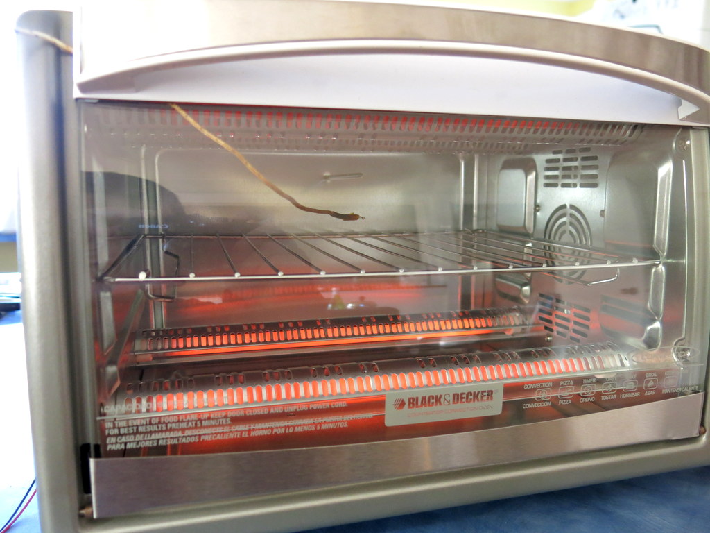
A reflow oven comes in handy when you work regularly with SMT circuits. I’ve had the T-962A reflow oven for about a year now. While it has worked reasonably well, recently it has started showing some signs of aging. First of all, the total reflow time is quite long, about 15-16 minutes. This is really slow. Worse even, occasionally the internal temperature sensor would have a hiccup and the boards would come out under-heated or over-heated. Also, I hate the built-in buzzer, which produces a very loud, high-pitched beep when reflow is completed. This is very annoying — since I keep the reflow oven outdoors, I didn’t want my neighbors to think the beep is my fire alarm. So it’s time to find an alternative / backup solution.

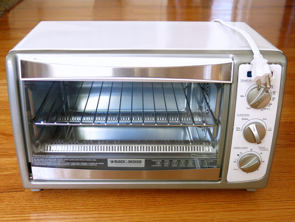
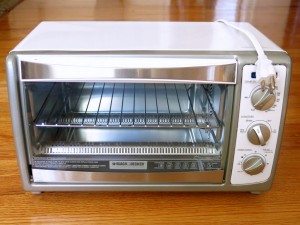
After some online research, I’ve decided to build a reflow toaster oven using an Arduino-based controller. Toaster oven is cheap and provides better, more even heating than a hot skillet. I know toaster oven reflowing has been blogged about everywhere, but I do want to give my version some bells and whistles to provide more convenience. For example, I typically keep the reflow oven outdoors on my porch while working in the basement. So I’d like to receive a remote notification when reflow is complete (no loud beep please!). Also, I’d like an automatic way to open the oven door and blow air into the oven to accelerate the cooling time. For remote notification, I’ve decided to use an 433MHz RF transmitter to send signals to a remote power socket. I have a lamp connected to the power socket, and this way I will get notified when reflow is done. For faster cool-down time, I will use a servo tied to the oven door handle with a string — rotating the servo shaft can pull the door open. I will also put a second remote power socket connected to a circulation fan to blow air into the oven. Since I am using remote power sockets anyways, I am going to throw in a third one for the oven. This way all power line devices are controlled by power sockets, so there is no messing around with cutting cables etc. If you want better reliability, you can certainly use a relay or an SSR. I just decided to go with RF power sockets for the convenience.


Materials
Here is the list of materials I used:

IMG_3591IMG_3593IMG_3594IMG_3595
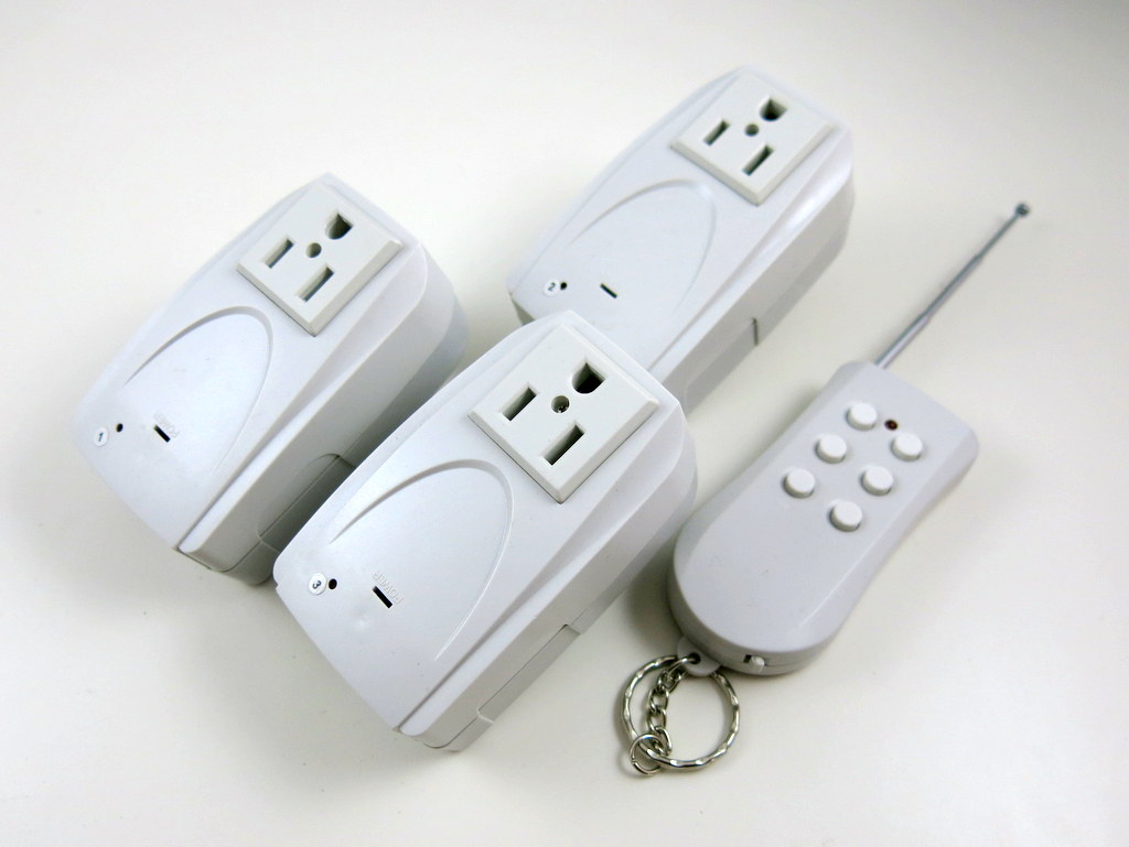
I have an existing set of RF power sockets and I don’t remember where I got them. But the link provided above looks similar, so they should work fine. A quick note: there are cheaper RF power sockets which only support toggling, but I would suggest getting the type that has separate on/off buttons for each channel, because you can know for sure whether the socket is on or off. Also, there are some types which work in the 315MHz frequency band. In this case, you need to get 315MHz RF transmitter instead of 433MHz.


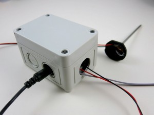
Step 1. Temperature Probe
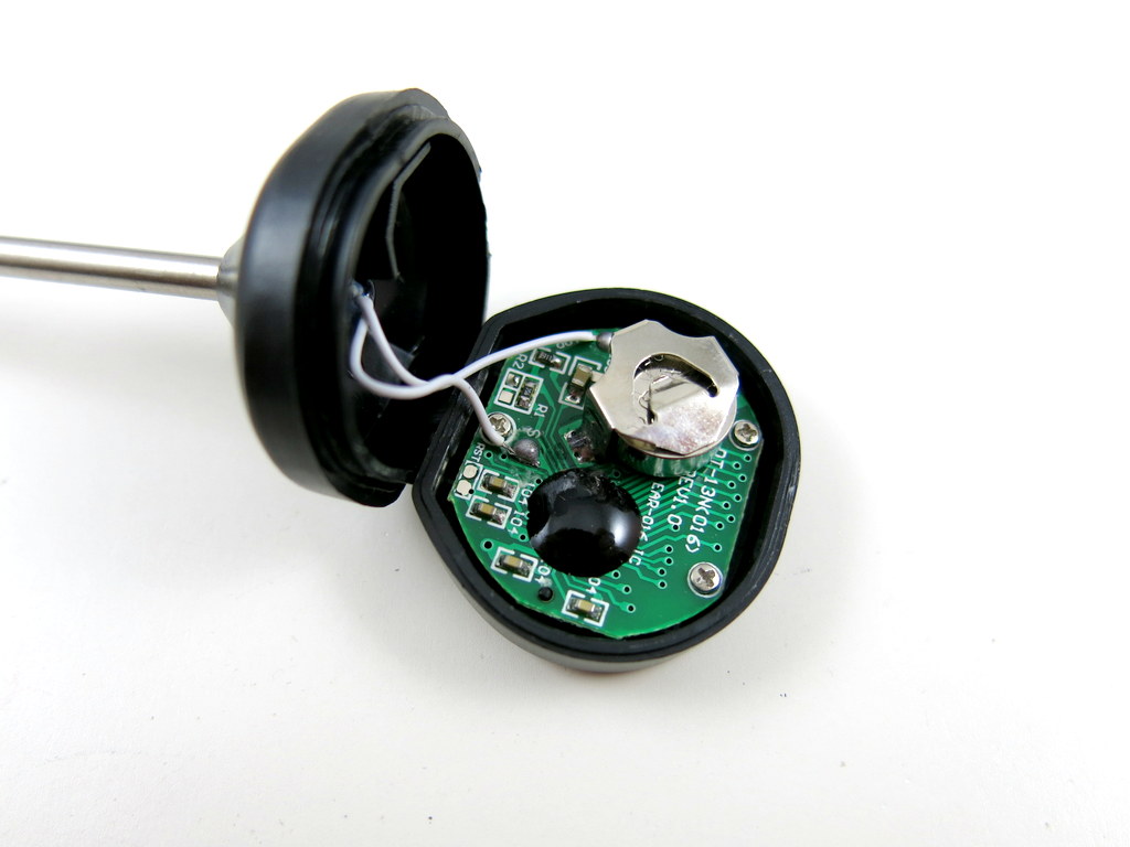
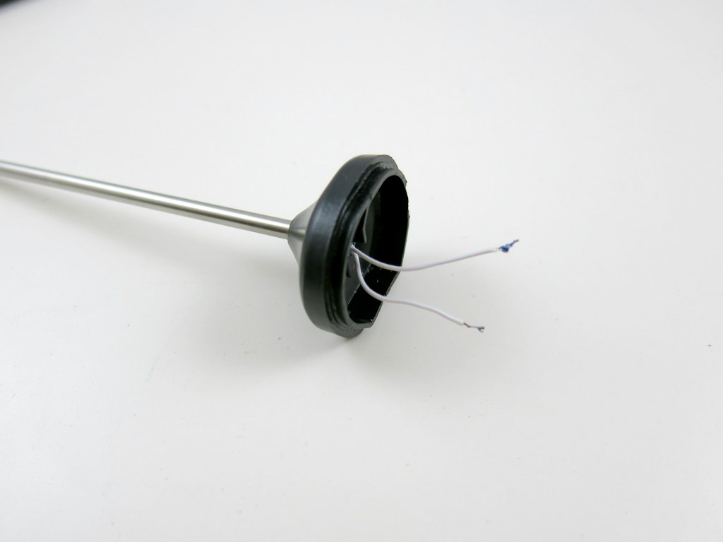
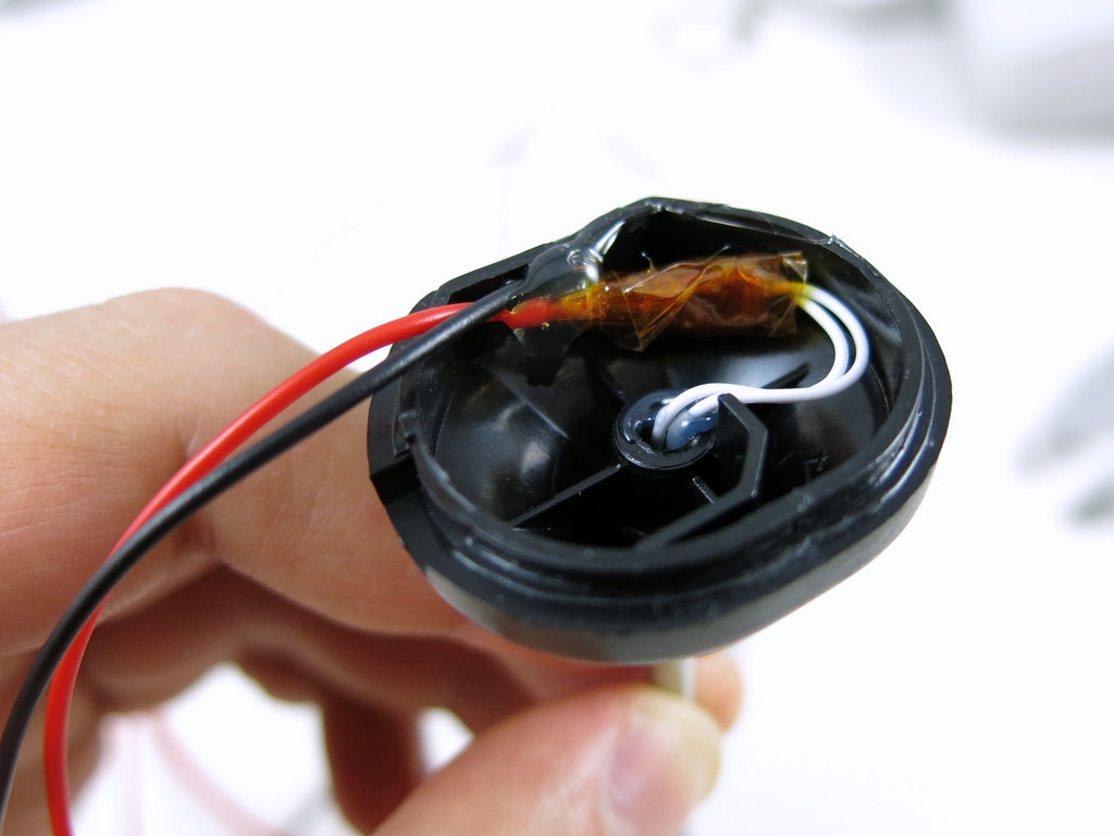
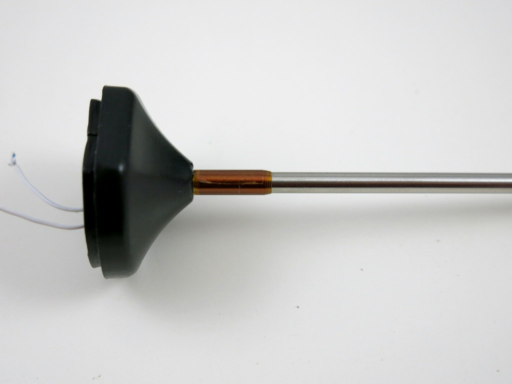
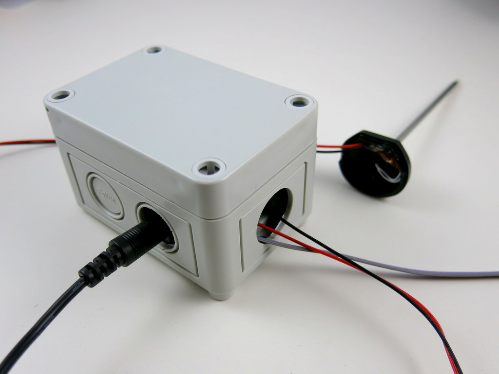
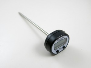
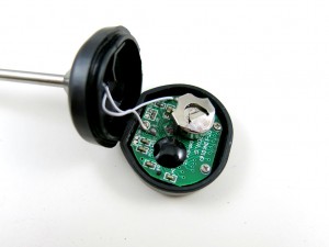
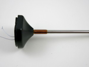
The reflow oven is a temperature-controlled device, so the first thing to do is to have the microcontroller sense temperature. The cheap kitchen thermometer is perfect for this: it has a thermistor (i.e. temperature-sensitive resistor) wrapped around a metal probe. Just open the thermometer, desolder the two wires, and extend the wire length by soldering two pieces of longer wires. I also used some hot glue to fix the joints so they they won’t move around and break.

IMG_3597IMG_3598IMG_3607IMG_3596

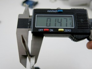
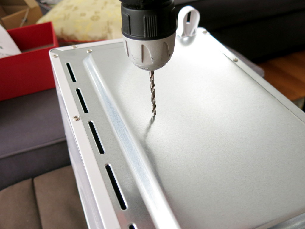
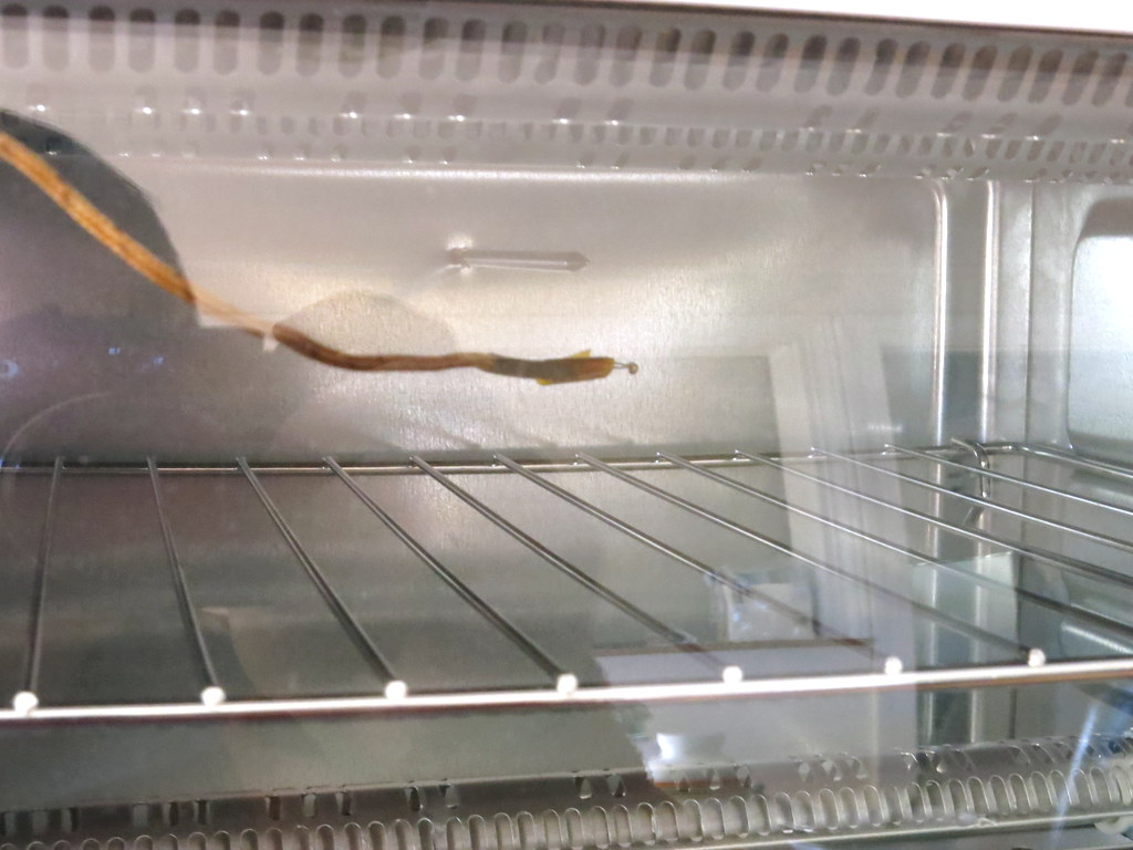
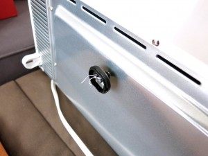
Next, measure the diameter of the temperature probe (mine is about 0.147″), and at the back of the toaster oven drill a hole that’s slightly bigger (I used 5/32 drill) than the probe size. The hole should be located at roughly a quarter to one-third on the height, so that when the probe is plugged in it would neither touch the top heating element nor the tray. Next, wrap a layer of Kapton tape around the temperature probe, and insert it through the hole, so that it stays tight in place.

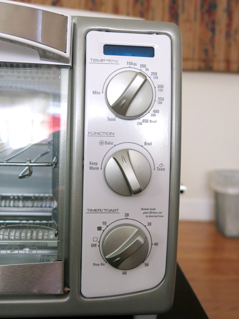
The oven should be set to the highest temperature, convection, and stay on. This way we can bypass the oven’s internal control mechanism and instead use the microcontroller to turn heating on and off.
IMG_3599IMG_3602IMG_3603IMG_3606

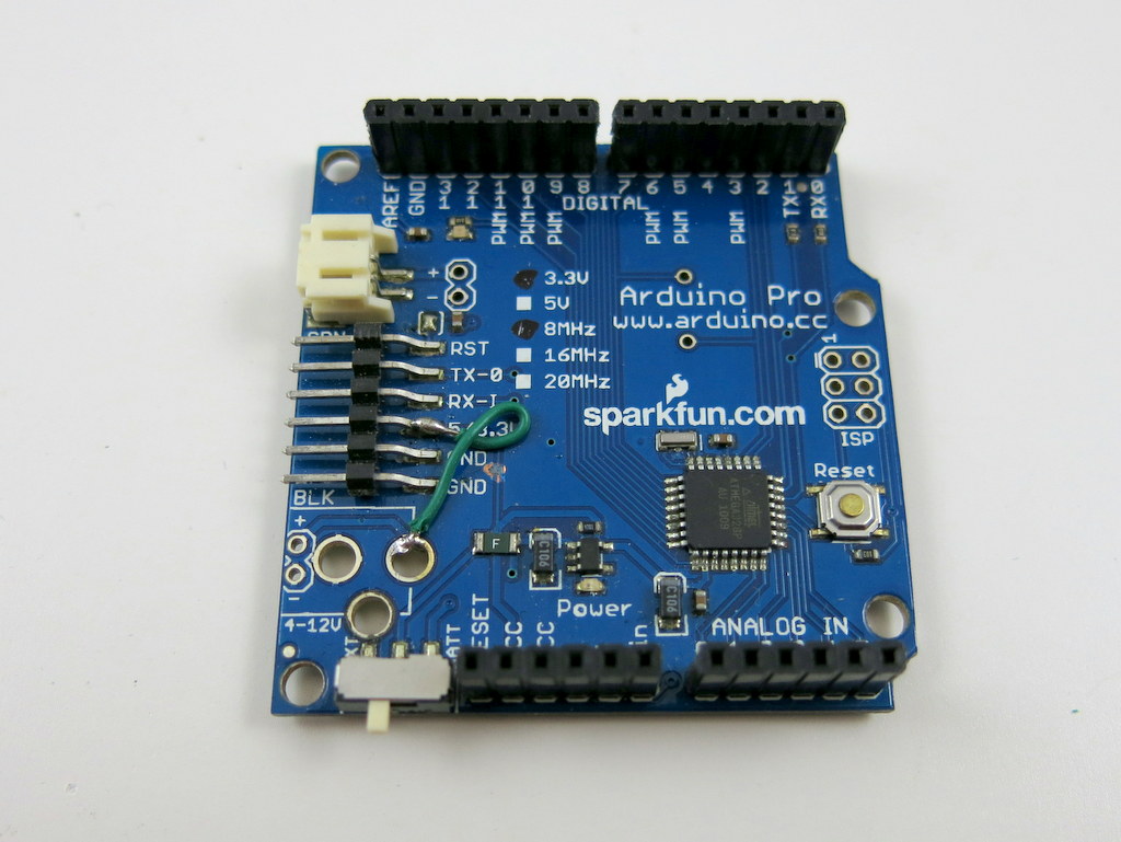
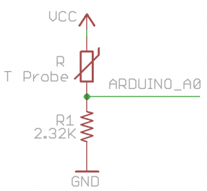
For the microcontroller to sense temperature, just use the 2.32K resistor to form a voltage divider with the thermistor (i.e. probe). See the schematic on the right below. The divided voltage is connected to Arduino’s analog pin A0 for reading.

IMG_3608t_volt_divider


Step 2. Temperature Calibration
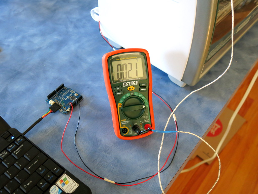
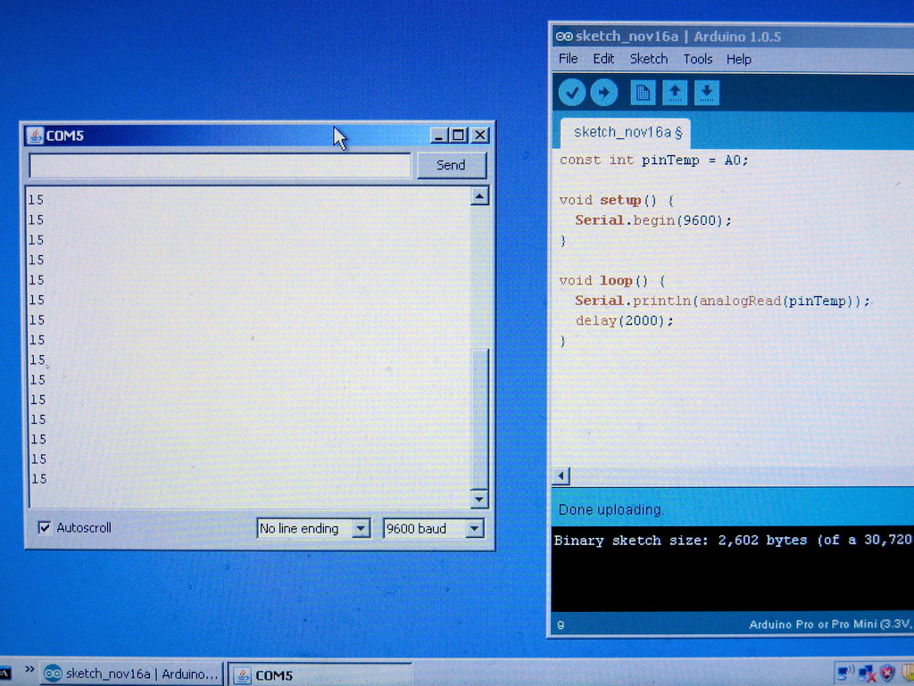
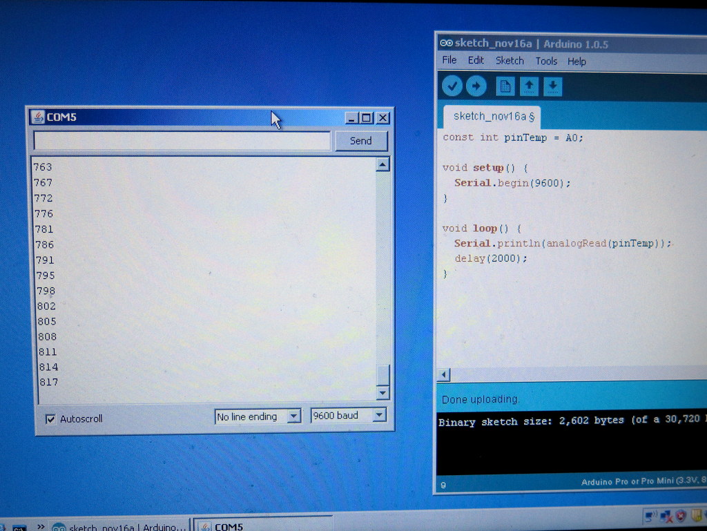
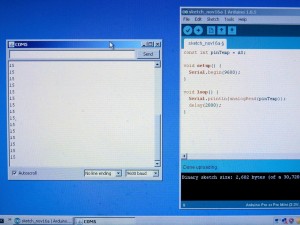
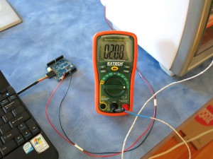
The next step is to perform temperature calibration. If you’ve got the same kitchen thermometer and 2.32K resistor as I have, you can skip this step. But if you have a different set, you need to perform a calibration step to find out the relationship between the actual temperature with the analog reading. To do so, I used an existing digital thermometer (my EX330 multimeter) to serve as reference. Insert its temperature probe to the oven and get the tip close to the center; then I wrote a simple Arduino program to print out analog values from A0 once every second. Turn on the oven to let it heat up. The temperature will rise, and the analog reading also rises.
IMG_3609IMG_3610IMG_3611

When it reaches about 210°C (Celsius), turn off the oven, and record the analog reading. Then do another reading when the temperature drops to about 170°C, and the last one when it drops to about 80°C. Basically 210°C is when we should stop heating (the temperature will climb up a little more beyond 210), 170°C is when the oven door will open and the fan will kick in, and 80°C is when the reflow is considered finished. My readings corresponding to these three temperature values are roughly 830, 790, and 360. These will be used in the Arduino program later.

IMG_3612IMG_3613IMG_3614


Step 3. Oven Door Opener
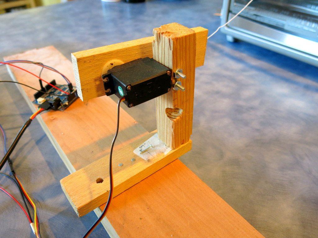
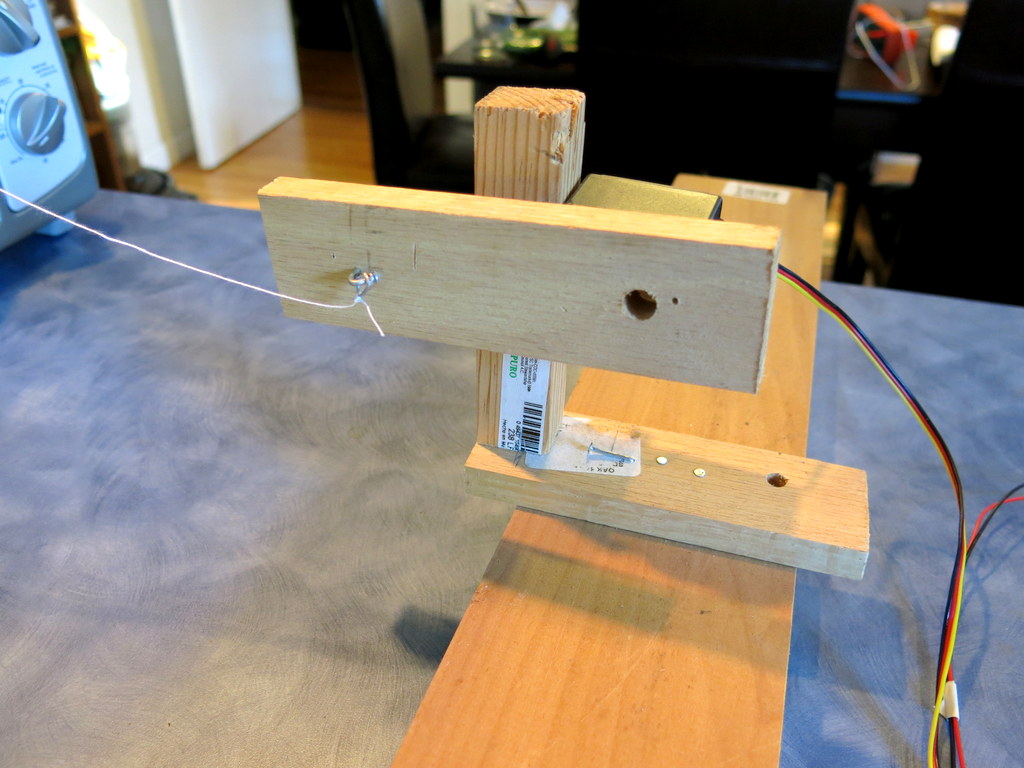
Next is a fun step. I built a oven door opener using a servo. The basic idea is to attach a piece of string between the servo and the oven door handle. Rotating the servo shaft will be able to pull the door open. To do so, I picked up some pieces of wood from HomeDepot and build a wooden frame. To make the whole assembly stable, the base of the frame should be sufficiently heavy. Then I secured the servo to the frame using some long #4 screws and nuts. Since the servo doesn’t come with a long shaft, I used a small piece of wood and attached it to the servo gear. This can extend the sweeping distance of the servo. Be careful not to make it too long though, otherwise you may overdrive the servo’s torque.
IMG_3620IMG_3621

The video below shows the servo in action. This is using Arduino’s built-in Servo example called Sweep. The servo’s three pins are connected to 5V, pin D9, and ground.


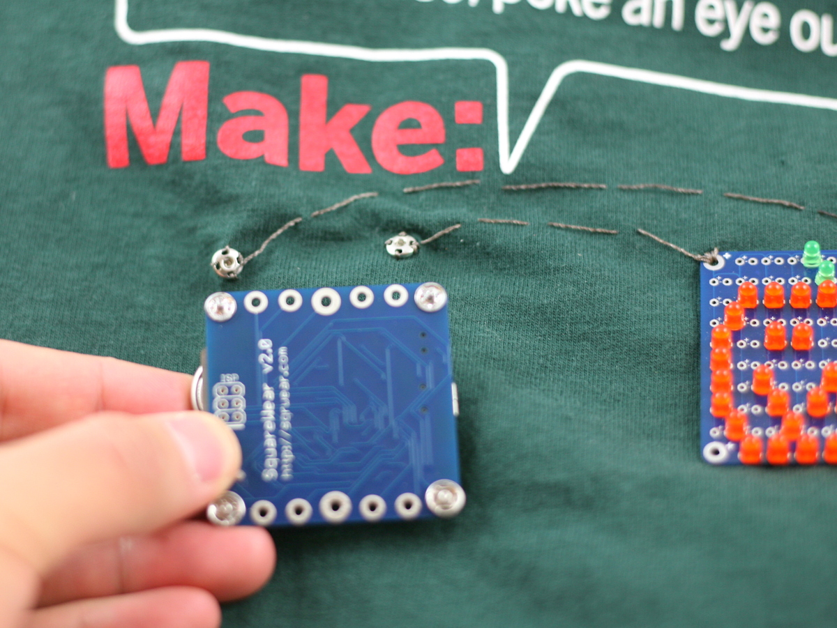
Step 4. Remote Power Sockets
The next step is to interface with the remote power sockets. I’ve written a previous blog post about this. Since then I have discovered the RC-Switch Arduino library. This is a very useful library that can automatically decode the signal patterns from most common remote power sockets. All that’s required is an Arduino and a RF receiver. I wired up my 433MHz receiver to the Arduino, and used the library’s receiver example to figure out the following binary code for my power sockets:

  • Channel 1 on: 010101010011000101000011; off: 010101010011000101000000.
  • Channel 2 on: 010101011100000101001100; off: 010101011100000101000000.
  • Channel 3 on: 010101010000110101110000; off: 010101010000110101000000.

Once the patterns are figured out, I can then connect a 433MHz transmitter to Arduino to simulate the remote control. This way I can reliably turn on and off each socket individually.


Step 5. Putting Everything Together and Testing
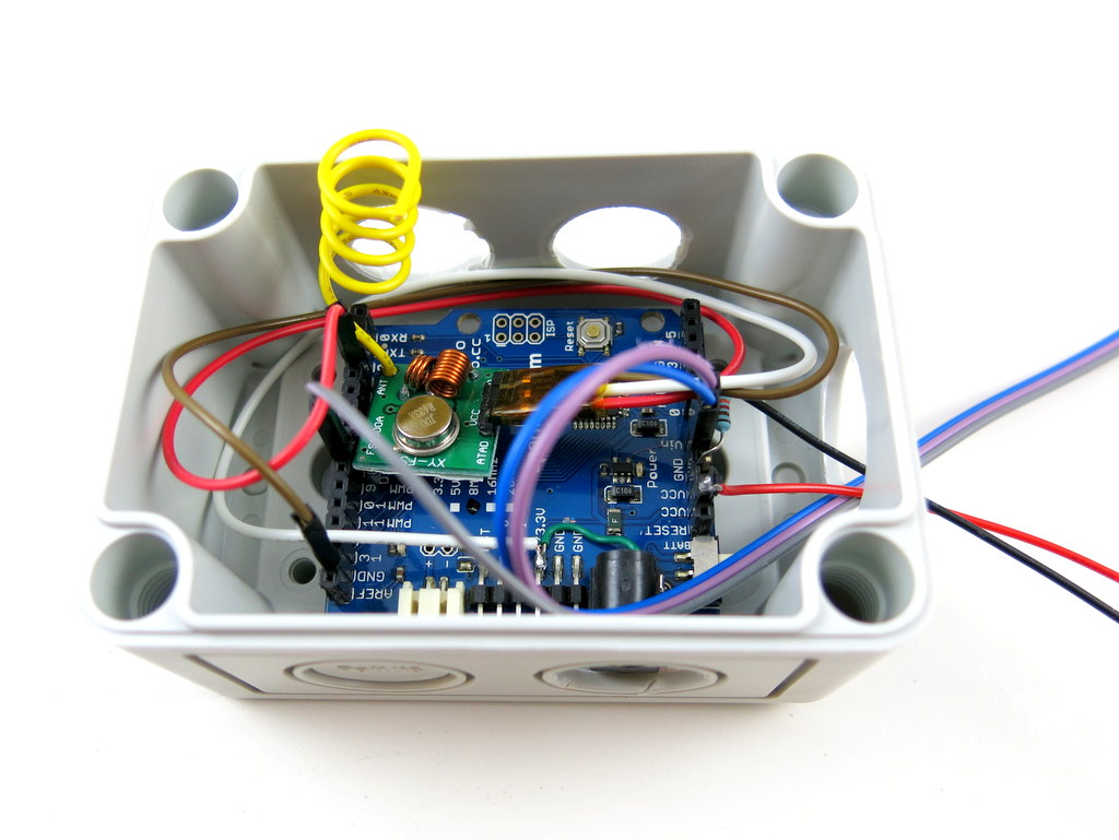
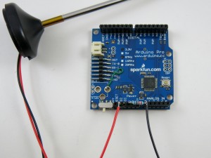
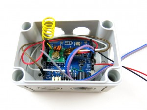
Now all the ingredients are ready, it’s time to put everything together for testing. The Arduino pin assignments are: temperature probe on analog pin A0, servo on digital D9, and RF transmitter on D10. The power sockets assignments are: toaster oven on channel 1, fan on channel 2, and lamp on channel 3. Since the controller will be used outdoors on the porch, I found an enclosure that can fit everything nicely inside. I also soldered a wire to the RF transmitter as an antenna to extend the transmission range. The power comes from an external 5V adapter. Please check the video at the beginning of the post for demonstration. The controller program source code can be downloaded here:

IMG_3622IMG_3623

With the capability of opening oven doors and blow air into it, the cool-down time is significantly faster. The total reflow time is about 6 minutes now, which is a lot better than 15 minutes before. That’s it, my reflow toaster oven with bells and whistles. It can certainly be improved by adding PID control, The hardware cost, everything included, is about $120. It’s inexpensive and pretty easy to replicate. Much better than my professional reflow oven!


  • OpenSprinkler Beagle kit is available for purchase at Rayshobby Shop.

Following the sneak-peak preview, I am excited to announce that OpenSprinkler Beagle (OSBo) v1.0 is now officially released! OpenSprinkler Beagle is an open-source sprinkler / irrigation extension board for the BeagleBone Black. It uses four GPIO pins to control an unlimited number of sprinkler valves. Using this board, you can easily convert your BeagleBone Black into a low-cost, web-connected smart sprinkler controller. You can use online weather data to help regulate sprinkler water time, and remotely change settings and programs when you are traveling away. Best of all, it’s an open-source project — you are welcome to tinker with the hardware and/or software to create your own customized sprinkler controller.

osbo_headerosbo_3

The idea of OpenSprinkler Beagle came from the OpenSprinkler Pi, which is a sprinkler extension board for the Raspberry Pi. Since OpenSprinkler Pi was released earlier this year, it has been a very popular product. Over time I’ve received requests from users to develop a similar board for the BeagleBone Black. While the BeagleBone Black is similar in nature to the Raspberry Pi (i.e. both are low-cost embedded Linux boards), it offers some interesting benefits such as a large number of GPIO pins, build-in analog pins, build-in eMMC, microSD card slot (i.e. smaller profile). faster CPU etc. Undoubtedly it makes sense to develop an OpenSprinkler variant for the BeagleBone Black.

The hardware design of OpenSprinkler Beagle is similar to OpenSprinkler Pi: it contains a 24VAC to 5VDC switching regulator, shift register, triac, DS1307 RTC with CR1220 battery, zone expansion board connector. It also currently shares the same enclosure as OpenSprinkler Pi. But it also offers several improvements, specifically:

  • Added a total of 10 bidirectional TVS for protection against transient voltages: one for each of the eight stations, one for the 24VAC port, and one for the rain sensor port.
  • The BeagleBone Black is now plugged down into OSBo, and all GPIO pins are mapped out to the pinout area.
  • Added a 5V mini-relay for more general-purpose switching. The relay has a contact rating of 120VAC / 2A. It can be used for switching low-power lighting, or garage doors etc.
  • The 24VAC terminal block is changed to orange color with 3.96mm pin spacing. This helps prevent incorrect connection to other terminal ports. There is also a solder-on 2A fuse on the 24VAC line.
  • Added a rain sensor port with pull-up and current limiting resistors.

Below is an annotated diagram that shows the various components of the board:
osbo_v10_diagram_interface


OpenSprinkler Beagle Homepage

Below I am going to give a very brief overview of the hardware and software setups. For details, please watch the tutorial video above, and visit the official OSBo homepage at http://beagle.opensprinkler.com.

Hardware Setup

The hardware is pretty easy to set up. The kit comes with an assembled OpenSprinkler Beagle circuit board, enclosure, screws, terminal blocks, and extra pin headers in case you want to map out additional GPIO pins. In addition, you need to provide a BeagleBone Black, a nano-size WiFi dongle, and a 24VAC sprinkler transformer (these are not included in the kit and need to be purchased separately). The board makes use of the first 2×10 pins on port P9 of the BeagleBone Black for interfacing with shift register, RTC, rain sensor port, and mini-relay. Plug in the BeagleBone Black into OSBo, connect the 24VAC power, plug in the common (COM) wire and individual station wires, and that’s it. The interface is the same with other sprinkler controllers. If you have a rain/freeze sensor, you can connect it to the rain sensor terminal.

Software Setup

Follow the recent update on OpenSprinkler Pi, the software setup for OSBo has also been made a lot easier. Specifically, I’ve created a SD card image with pre-installed software. Download the image, burn it to a microSD card, pop it in to your BeagleBone Black, and you are ready to go. The pre-configured SD card runs a Ubuntu operation system (default user name ubuntu, password temppwd), and sets Dan’s interval_program to start by default. As soon as the system has booted and is up online, you can open a browser and type in http://x.x.x.x:8080 (where x.x.x.x is your BeagleBone’s IP address). This will bring up the interval program’s web interface. The interval program has a rich set of software features, such as setting multiple sprinkler programs, preview programs, run-once program, manual operation, logging, rain delay etc. The details are all explained in the user manual of the interval program.

The SD card has also pre-installed Samer’s mobile web app, which provides a nice front-end for mobile devices such as pads and phones. It is available at http://x.x.x.x/sprinklers.

In addition, there are three demo programs installed in the /home/ubuntu/demos/ folder. There is a self-test program, a relay test program, and a Google Calendar-based sprinkler program, which makes use of a Google Calendar for scheduling water events. I’ve received many good comments regarding the Google Calendar-based program — while it looks simple, it’s quite convenient to use and very suitable for the less technical minded people.

Since the software is pretty much all adapted from OpenSprinkler Pi, feel free to refer to the OpenSprinkler Pi documents if anything is unclear. I will try to make the OpenSprinkler Beagle website more self-contained, and it will have to be polished over time.

Naming

In the previous post, I asked for naming suggestions. Thanks to everyone who made comments there. After careful thoughts, I’ve decided to use the full name OpenSprinkler Beagle, and short name OSBo. Particularly, the short name OSBo is picked because it goes well with OSPi (OpenSprinkler Pi), is easy to distinguish with OSBee (openSprinkler Bee), and Bo is a name of a dog. So overall I consider this to be the top choice.

Thanks for reading this post. If you are interested in buying the OpenSprinkler Beagle, we have a limited number of kits immediately available, at the first link below. Feel free to leave comments and suggestions below or at the Rayshobby Forum.

Links


An OpenSprinkler Pi user Michael Wilson sent me this nice illustrated document he wrote about setting up OpenSprinkler Pi and the mobile web app. He successfully installed OpenSprinkler Pi to replace his previous Toro controller. The document has somehow slipped out of my mind and has been sitting in my mailbox for a few months. I should have posted it when I received it! Anyways, thanks Michael for sharing it with us!

Download as PDF

This post is a direct update of the post I wrote in September during my visit to SeeedStudio. Today I received the official sample of the OpenSprinkler paper box. Check the photos below. Very cool!

IMG_3507IMG_3508

IMG_3509IMG_3510

The paper box was designed by SeeedStudio, and hopefully it will give OpenSprinkler a more professional touch.

The other piece of news is that we’ve finalized the new zone expansion board enclosure design. This is going to be injection molded soon. Below are pictures of the 3D printed prototype. The style follow the OpenSprinkler injection molded enclosure, so they will have a consistent look. The new design allows 16 stations per zone expansion board, yet the board size is roughly the same with the current 8-station zone expansion board. So it’s really really compact. This will probably become available in the first quarter next year.

image004image005

image006image007


Update: information on this blog post is outdated. Please check the latest instructions in the OSPi v1.4 user manual.


Good news to OSPi users: a pre-configured SD card image is now available for download at the following url:

NOTE: OSPi v1.4 requires either a microSD card or a low-profile SD card (due to the limited space in the enclosure). A microSD card adapter for RPi is included in the kit.

The image is compressed from an existing OSPi installation that contains Dan’s interval_program, Rich’s sprinklers_pi program, Samer’s OpenSprinkler mobile app, and the Google Calendar-based scheduling program. Download it, burn it to an SD card, and pop it in to your Raspberry Pi. Then you will be ready to go right away. No more pulling your hair or banging your head against the wall (well, hopefully :))!

The process to burn the image to an SD card is the same as burning a raspbian image to SD card. If you’ve used Raspberry Pi before, you’ve probably done this already, maybe even multiple times. If not, you should check the detailed online instructions here: http://elinux.org/RPi_Easy_SD_Card_Setup

Here is a quick summary:

  • Decompress the image file to your computer.
  • Insert an SD card (4GB or above). Make sure you back up any important file on the SD card as the procedure below will overwrite the content on the SD card.
  • Depending on what operating system you use:
    • On Windows, use the Win32DiskImager software.
    • On Mac, use the ‘dd’ command in a terminal, for example: sudo dd bs=1M if=name_of_the_image_file of=/dev/partition_to_burn_to
    • On Linux, the same, use the ‘dd’ command on a terminal, for example: sudo dd bs=1M if=name_of_the_image_file of=/dev/partition_to_burn_to
    • VERY VERY IMPORTANT: make sure you have selected the correct drive name (or partition name) to burn the image to!!! If you’ve selected the wrong drive, you might end up wiping out your computer’s hard drive, and I am sure you will be back pulling your hair again!!! Double check before you press enter or click on confirm.

Once the SD card is ready, pop it in to your Raspberry Pi. Since WiFi is not configured yet, you should first connect it directly to your router using a wired Ethernet cable. Alternatively, if you are a Linux user, insert the SD card to your computer, and you directly edit the WiFi SSID and password in file /etc/network/interfaces on the SD card (not your computer!). This way when you pop it in to RPi, it will automatically connect to your WiFi network.

In your home router’s configuration page, find out the IP address assigned to the Raspberry Pi. Next, open a browser, and type in:
http://x.x.x.x
where x.x.x.x is your Raspberry Pi’s IP address. You should see a page with further instructions, such as setting up time zone, WiFi etc. If you can see this page, congratulations, you’ve succeeded!

Dan Kimberling’s interval_program is set as the default program to run on start-up. Type in the following url in a browser:
http://x.x.x.x:8080
(again, x.x.x.x is your Raspberry Pi’s IP address) and you should see the web interface of the interval_program.

The OpenSprinkler mobile app is also pre-installed to the SD card, which is available at:
http://x.x.x.x/sprinklers

You can also switch to run Rich Zimmerman’s sprinklers_pi program on start-up. To do so, ssh (or use a monitor and keyboard) to your Raspberry Pi (the system uses the default user name pi and password raspberry) and run the script in a terminal: sudo /home/pi/select_program. Once you’ve switched to the sprinklers_pi program, you can access its web interface at the same http://x.x.x.x:8080.

These have all been explained in the one-page instruction. For questions, comments, and suggestions, please post them at the Rayshobby Forum: http://rayshobby.net/phpBB3. Thanks!

4gsd

« Newer Posts - Older Posts »