Feed on
Posts
Comments

Update: the technique described in this article is possibly no longer necessary for the current version of OSBee, as it now supports setting a different opening vs. closing voltage.


Recently when helping a customer, I came across an interesting case of how to control Gardena 1251 latching solenoid valve using OpenSprinkler Bee. This valve is mostly sold in the European market and isn’t very popular in the US market. On spec, it’s operated using a single 9V battery, and to use this valve you need to buy a Gardena 1250 controller unit. The whole assembly including the valve and controller unit are quite pricy (close to 100 bucks), so it’s not a very cost-effective solution compared to other brands. Nonetheless, it’s an interesting case that helped me understand how these latching solenoids work.


Measure the Control Voltages

The initial request to look into this valve was due to the fact that OSBee can’t seem to operate this valve correctly: it can open the valve but never manages to close the valve. This was reported by a German customer, and it caught my curiosity. To figure out the issue, the first thing I did was to check how the control unit (1250) is sending out control voltages to the valve. It’s pretty common that when operating latching solenoid valves, the control circuit sends an impulse voltage to open the valve, and another impulse voltage in the reverse polarity to close the valve. On most solenoid valves I’ve seen, the two impulse voltage (of opposite polarity) are roughly the same, and that’s also how the OSBee circuit works.

Upon connecting the control unit to an oscilloscope, I noticed something strange: no matter how I press the on/off button, it’s only sending a very short (a few milliseconds) pulse, which cannot possibly operate the valve. Then it became clear to me that the controller is in fact actively sensing the existence of the valve, and would not send control voltages if the valve is not detected. I measured the resistance of the solenoid valve, which is about 35 ohm. So I connected a 33 ohm resistor to the controller as a dummy load, and there you go, now we can observe the control voltages and pulse lengths.

It’s pretty easy to notice the asymmetry here: while opening the valve requires a pulse of 250 ms and -7.84 voltage (this is roughly the battery voltage since my 9V battery isn’t fully charged), closing the valve only requires a very short pulse of 62 ms and very low voltage — 2.5V. This is quite strange to me: how come closing the valve only requires such a short pulse and such low voltage?


How Does This Latching Valve Work?

In order to figure out what’s going on here, I un-tightened a bunch of screws and opened up the valve.

At the bottom of the valve is a pressure chamber with a spring. This is very similar to other valves I’ve seen.

The top section contains, supposedly, a coil and magnet inside, and a small cone-shaped metal piece that can be attracted to the magnet or released. It’s quite easy to observe that when opening the valve, the metal piece gets attracted (left picture above), this supposedly releases the pressure in the bottom chamber, thus allowing the water to flow through the valve. Conversely, when closing the valve, the metal piece is released and dropped to block the hole at the bottom, this supposedly allows water pressure to build up in the bottom chamber, thus stopping the water flow.

The key in making this latching is that an impulse voltage can permanently magnetize the core, thus permanently attracting the metal piece. This makes it possible for the valve to remain in the ‘open’ status without contiguously drawing current from the power source (which is unlike non-latching valves like 24VAC valves).

Observing this mechanism, it became clear to me that ‘closing’ the valve basically requires de-magnetizing the core, and that requires just a short pulse of low voltage in the opposite polarity. If you apply the same voltage and strength as before, it will start magnetizing the core the other way, thus the magnetic pole changes direction but the metal piece will still be permanently attracted!

Anyways, this is very interesting to me because previously I had no idea how latching solenoid valves work internally. Now at least I know understand this particular valve works, and this understanding will help me figure out how to get OpenSprinkler Bee to control this valve.


Use OSBee to Control the Gardena 1251 Valve

There are several issues that make OSBee incompatible with the Gardena 1251 valve, but it turns out they can all be solved without too much difficulties. The first is that OSBee by default boost the input voltage (which is 5V from USB) up to 22VDC, which is significantly higher than 9V required by the valve. This is reasonably easy to solve — by fine tuning the boosting time, I can find the sweet spot where the boosted voltage is just around 9V. This boosting time turns out to be around 80 to 100ms.

Second, OSBee by default uses 100ms pulse in both directions (i.e. both opening and closing the valve). This is very easy to change to 250ms and 62ms respectively to match the Gardena controller.

The last issue deserves more thinking, that is, opening the valve requires 9V, but closing the valve requires only 2.5V. Because the input voltage is from USB and it’s 5V, there is no obvious way to step that down to 2.5V since the boost converter can only bump up the voltage and never reduce the voltage. How do we create this asymmetric voltage in opposite polarities? Turns out that you can do so by making use of a diode connected in parallel with a 100 ohm resistor. Why? The diode is a one-way gate: when positively biased, it turns on almost fully (except the 0.7V voltage drop across it, which can be ignored here); but when reversely biased, it turns off, thus current has to flow through the resistor (connected in parallel to the diode), and that resistor will divide the voltage, ensuring that only about 2.5V falls on the valve.

I’ve attached here a diagram showing the connection. The diode can be almost any general-purpose rectifier, like 1N4148, 1N4001 and so on. I’ve also included two photos showing the actual components connected to OSBee and the valve. With this modification, OSBee can now both open and close the Gardena 1251 valve successfully. Mission accomplished!

Today I am very excited to introduce OpenSprinkler Bee (OSBee) 2.0: it’s an open-source, WiFi-enabled, universal sprinkler controller. It is suitable for garden and lawn watering, plant and flower irrigation, hydroponics, and other types of watering project. This is the first OpenSprinkler product built upon the popular ESP8266 WiFi chip. It’s designed primarily for latching solenoid valves, but can also switch non-latching solenoid valves (such as standard 24VAC valves), low-voltage fish tank pumps (which can be used to feed water to flower pots and indoor plants), and other types of low-voltage DC valves and pumps. All of them can be powered from a single USB port. This is made possible by using a unique circuit design that leverages a boost regulator and a new solenoid driver circuit. Hence I call it a Universal sprinkler controller. Among the software features, it introduces the concept of Program Tasks, which provides maximal flexibility in programming the zones. In contrast to the first version of OSBee, which was in the form of an Arduino shield and relies on an additional Arduino, OSBee 2.0 is a standalone controller with built-in WiFi, OLED display, laser cut acrylic enclosure, and can switch up to 3 zones independently.

Here is not-so-short video introduction to OSBee 2.0:

Here are two photos of the OSBee 2.0 circuit board:

osbeewifi_1osbeewifi_2

Screenshots of the web interface and Blynk app:
osbee_screenshots

In summary, in terms of Hardware Design, it has the following features:

  • A single ESP8266 chip serves as the microcontroller and handles WiFi connectivity.
  • On-board 128×64 OLED display, real-time clock with backup battery, USB-serial chip. Can switch up to 3 zones independently.
  • Boost converter and a new H-bridge design that allows the same controller to switch both lathing and non-latching solenoid valves, all powered from a single 5V USB port.
  • An easy-to-assemble laser cut acrylic enclosure.

In terms of Software Features:

  • It has a built-in web interface that allows you to easily change settings, perform manual control, and create automatic sprinkler programs. It also provides logging and program preview features.
  • It introduces Program Tasks to allow maximal flexibility in programming zones. For example, you can define arbitrary ordering of zones, have multiple zones run at the same time, and insert delays between tasks. Zone water time is programmed at precision of seconds.
  • It allows remote control through the Blynk app and Blynk cloud server.
  • Firmware update can be performed either wirelessly using the web interface (OTA), or through the on-board USB port with a USB cable.

It improves upon the current OpenSprinkler 2.3 by adding built-in WiFi capability, and using a unified solenoid driver that can handle both latching and non-latching solenoid valves. On the other hand, it can only switch up to 3 zones, and the number cannot be expanded. It’s also missing a few advanced features at the moment, such as weather-based water time, virtual stations (e.g. HTTP and RF stations), and support for sensors. Some of these features are purely software, and can be easily added in the future.

OpenSprinkler Bee 2.0 is now available for purchase at our online store:

The package includes a fully assembled OSBee 2.0 circuit board, laser cut acrylic enclosure, instructions, USB cable, and optionally an USB adapter.


Resources and Technical Details

OSBee 2.0 is an open-source project. Its hardware schematic, firmware source code, user manual, and API document are all available at the OpenSprinkler Github repository (look for the prefix OSBee in the repository).

Below I will briefly go over the technical details of the boost converter and the solenoid driver, as I think it’s an interesting design that’s potentially applicable elsewhere. The boost converter is borrowed directly from the OpenSprinkler DC circuit. It’s a simple MC34063-based boost regulator that bumps the input 5V up to 24V DC, and stores the charge into a 2200uF capacitor.

osbee_circuit_1

The Booster is controlled by two MOSFET-based high-side switches. The first one controls the input power: the microcontroller uses it to feed the input 5V to the booster, which quickly raises the voltage to 24V. After a couple of seconds, high-side switch 1 is turned off and the microcontroller prepares the states of the half H-bridges (COM, Z1, Z2, Z3). Let me first explain how the states are set for Latching solenoids. The solenoids for the three zone are connected between COM-Z1, COM-Z2, and COM-Z3 respectively. Normally all four half bridges are in ‘High’ state, so the net voltage across every solenoid is 0. To activate a solenoid (say Z1), the corresponding half-bridge will be pulled down to ground (i.e. ‘Low’ state). The microcontroller then turns on high-side switch 2 momentarily to dump the charge from the 2200uF capacitor to the solenoid. This turns on the valve. To deactivate the solenoid, the microcontroller pulls all half-bridges to Low, except the zone that is to be deactivated which remains in High state. It then turns on high-side switch 2 momentarily, again dumping the capacitor charge to the solenoid, but now in reverse polarity, thus closing the valve. This is basically how it operates latching solenoids.

So how does the same circuit work for Non-Latching Solenoids, such as 24VAC valve commonly used in residential sprinkler system? It turns out that just like latching solenoids, non-latching ones also require a pretty high impulse current (called inrush current) to get activated. The difference, however, is that to keep it on, it needs to draw current continuously from the power source. When the power cuts off, the solenoid is deactivated. This is called the holding current and is considerably lower than the inrush current. So to operate non-latching solenoids, all I need is an additional diode that provides a path from the input 5V to the solenoids to provide the holding current. This diode could be software switched by the microcontroller, but because ESP8266 has very few number of GPIO pins, (and I want to avoid having to use an IO expander), I opted to enable this diode path using a solder jumper. To operate non-latching valves, this jumper needs to be soldered on.

osbee_circuit_2

On the Software side, the firmware uses an option to allow the user to choose the valve type (unfortunately the controller can’t automatically detect the valve type yet). For non-latching valves, the half-bridge states are actually easier to manage than the latching case: now COM is always in ‘High’ state, and Z1, Z2 or Z3 are kept ‘Low’ for as long as needed to keep the valves on. That’s it.

You may be wondering how does this even work for valves rated at 24VAC? How can we drive them using DC, and just 5V? The short answer is that this is due to the way such solenoids behave under AC. Specifically, when you first connect the solenoid to 24VAC, it immediately draws a high inrush current, which reliably energizes the solenoid and opens the valve. Once energized, the solenoid presents a large inductance and high reactance to AC, thus limiting the effective current flowing through it. This results in lower holding current, which is enough to keep it on and saves the coil’s lifespan. We can exploit this behavior and achieve the same effect using a DC-based circuit: the booster produces a high voltage initially to provide the inrush current needed to energize the solenoid, and then lowers the voltage to the input level to provide the holding current. Exactly how much holding current is needed is not clearly defined, but for all 24VAC solenoids I’ve tested, once energized, they can remain on at just 5V input voltage.

Now we are left with the last part of the technical details: the Half H-Bridge Design. From the circuit diagram above, it seems we can easily implement the half bridges using relays. While this is totally true, relays are bulky, expensive, slow to switch, and difficult to replace. For these reasons, modern electronics prefer to use semi-conductors as much as possible in place of relays. So I decided to use a MOSFET-based H-Bridge design, and it’s a more interesting design than just throwing relays everywhere.

Typically when you want to switch between GND and a voltage considerably higher than the microcontroller’s output, you can use a half H-bridge design as show in the left image below. It uses a low-power N-MOSFET to drive the high-power P-MOS on the bridge, making it possible to use a GPIO pin to switch a high voltage. However, this generally requires 2 GPIO pins (i.e. A and B) per half bridge. Because ESP8266 has a small number of GPIO pins, the challenge is how to use just 1 GPIO pin per half bridge.

osbee_hbridge_1osbee_hbridge_2

So I came up with a slightly modified half bridge design, as shown in the right image above. It leverages two low-power N-MOSFETs to drive the high-power P-MOS and N-MOS on the bridge. This allows using just 1 GPIO pin (A) to switch the bridge. When A is Low, both input N-MOSFETs turn off, and the gates of the P-MOS and N-MOS are both pulled high, so the P-MOS turns off and N-MOS conducts, pulling the OUTPUT to Low. When A is High, the reverse happens, and the OUTPUT is also High.

Using two input N-MOSFETs also makes it easy to prevent shoot-through problem, which is often an issue with H-bridge. Shoot-through happens when the control signal A transitions from Low to High (or conversely from High to Low), and at some point the P-MOS and N-MOS may both be in conducting state, causing a shorting. To avoid this, I chose to use two different types of input N-MOSFETs: one with lower gate threshold voltage (such as BSS138) and one with higher gate threshold voltage (such as 2N7002). This way, as the control signal A swings between Low and High, the two input N-MOSFETs will turn on and off at different times, ensuring that the P-MOS and N-MOS will not both conduct at the same time. As for the choices of the P-MOS and N-MOS, I opted to use the common AO3401 and AO3400, which provide ample room for continuous current as well as impulse current.

Sorry about going through these nitty-gritty details, but I think these are interesting design notes worth documenting and sharing. Feel free to chime in with your comments and suggestions. Thanks!

A quick note that our Black Friday / Cyber Monday sales are on now: all OpenSprinkler products are shown in discounted prices right now, and the deal only lasts till Monday Nov 28. This is the only time of the year that we offer discounted pricing, so if you are interested in buying OpenSprinkler, grasp this chance and don’t let it slip away!

If you are wondering whether you need to apply any coupon code. The answer is NO: the price you see is the discounted price. In the past when we used to have coupons, many customers forgot to apply the coupon in the end. To save you the trouble of having to enter coupon code, we directly discount the price, so you will definitely not miss it.

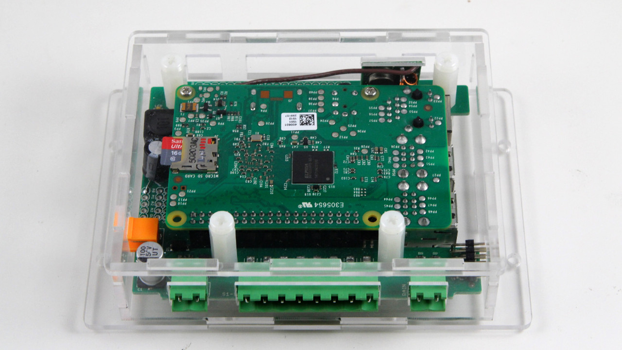
For a long time, OpenSprinkler Pi (OSPi) has been using the OpenSprinkler injection molded enclosure. While this has worked fine, the enclosure is not particularly designed for OSPi, leaving some cutouts not aligned with Raspberry Pi. Recently I have started learning to design enclosures using laser cut acrylic pieces. This is a great way to design fully customized enclosures for circuits. Today the first batch of laser cut enclosures for OSPi has arrived, and we will be shipping these with OSPi kit right away.

Here is a picture of the enclosure pieces and screw bag:
img_1262

And here is a picture of the enclosure after it’s fully assembled. After removing all the protective papers from the acrylic pieces, it produces a fully transparent look of OSPi, which is pretty cool.
img_1261

It’s not necessary to remove all the protective papers. I would recommend leaving the papers on except the top panel. This way it gives a kind of wooden texture of the enclosure, and adds more protection to the enclosure.

Below is an instructional video that walks you through the assembly steps:

I will make a separate post shortly that explains how to automate the design of such laser cut enclosures.

Hey, it’s March already, that means spring will be here soon! Amid an unusually cold winter and freezing weather this winter in New England, we’re finally starting to see some warm winter days. No more snow please, we’ve had enough 🙂

Ars Technica
This post is to give you some recent updates on OpenSprinkler and upcoming plans. First of all, OpenSprinkler Pi got blogged by Ars Technica, which is super cool. It’s really a fun article to read. That caused a huge spike of orders, but we managed. I only wish that Cyrus Farivar, the author, had talked about the microcontorller-based OpenSprinkler as well, because appearance-wise it looks more elegant.

Unified Firmware 2.1.3

Next, we just released the first version of the Unified OpenSprinkler Firmware, numbered 2.1.3. The biggest benefit of this firmware is that it’s cross-platform — it can compile and run on all OpenSprinkler hardware platforms, including the standard OpenSprinkler (OS), OpenSprinkler Pi (OSPi), and OpenSprinkler Beagle (OSBo). The cross-platform idea was inspired by Rich Zimmerman’s sprinklers_pi program. The purpose is to make a fully consistent firmware for OS, OSPi and OSBo, so that the same firmware and same features are available on all of them.

Technically, the unified firmware is written in C++. It’s done this way to share the code between OS, OSPi and OSBo as much as possible. The major differences are that on OS, all non-volatile memory data (such as options, program settings) are stored in EEPROM, while for OSPi/OSBO, these are stored in a local file, which simulates EEPROM. Also, OSPi/OSBo uses the standard socket to handle Ethernet communication, while OS uses an Arduino EtherCard library. Other than these, the code is largely shared between them, making it easy to extend in the future. Folks may find C++ based programs less friendly to modify than Dan’s Python-based interval_program. However, as I said, the point is to make the three platforms maximally compatible, so that any new features introduced in OS will be simultaneously available to OSPi and OSBo.

The main added new feature of this firmware is the support of using sunrise/sunset times in program settings. Specifically, the program’s first start time (and any of the additional start times) can be defined using sunrise/sunset time +/- an offset (in steps of minutes) up to 4 hours. The program preview will also take into account the sunrise/sunset time of a specific day. Another change is the support for MD5 hashed password, which attempts to address the previous plain-text password to some extent. For the security-minded, I admit that this is far from sufficient, but better than before.

For OSPi/OSBo, all features currently implemented on the OS, such as individual station water time, Zimmerman’s weather-based water adjustment, and support for radio frequency stations, are also immediately available for OSPi/OSBo.

Details on this firmware and how to upgrade OS/OSPi/OSBo to use this firmware can be found in this forum post.

Upcoming Plans
There are quite a few things on our todo list. The top items include:

  • Getting OpenSprinkler certified by the EPA WaterSense program (which requires ET-based water time calculation).
  • Support for soil moisture sensor and flow sense (at least flow estimation).
  • Improve the scheduling algorithm to better handle overlapping schedules using a queue.
  • Adding firmware support for using sensors (either digital or analog) to trigger sprinkler events.
  • Adding cloud-support (long term goal).

Some of these are purely software, but some will entail hardware changes. For example, for cloud-support, we’ve come to the conclusion that it will require an upgraded microcontroller due to the resource limitations of the current hardware. So the cloud support will likely not happen until OpenSprinkler 3.0 comes into place. It seems that adopting ATmega1284 is the most straightforward solution — it’s totally pin compatible with the current ATmega644, but doubles the flash memory space and quadruples RAM size. If you have suggestions about desired hardware changes, please feel free to let me know. This is the time that your opinions will be factored into the future of OpenSprinkler 🙂

Besides the additional new features, we are also planning to remove some features which are rarely used. One immediate plan is to remove the built-in relay, which seems not very useful, only to add manufacturing cost. The original idea of including a built-in relay is to use it for general-purpose switching, such as garage doors, landscape lighting etc. However, there is no cutout dedicated to the relay wires, so it requires some modification to the enclosure. Also, now that we have support for Radio Frequency (RF) stations, the need for build-in relay is even lower. Alternatively, you can use an external 24V AC relay, which I blogged about previously. At any rate, it seems wise to retire the built-in relay.

Retiring OpenSprinkler DIY and OSPi Standard Version
To prioritize our business, we have decided to permanently discontinue OpenSprinkler DIY kit and OSPi Standard version. We will no longer stock these kits. I know that OpenSprinkler DIY kit has been a fun product for many makers and Arduino lovers. But the maintenance cost is also pretty high — even though we do not officially provide technical support for DIY kits, in practice we still help users a lot in fixing their soldering mistakes and diagnosing issues. This has taken too much overhead, and because of this reason, we will retire the DIY kit.

As for the OSPi Standard version — it will also be retired soon in favor of the Plus version. Most of Raspberry Pi’s new products, including A+/B+/2 use the same form factor, which is not compatible with the original A/B. The standard version is still compatible if you own a RPi 1 model A/B. But we are looking into the future, and expect the orders of the standard version to drop significantly in the upcoming season.

DC Powered OpenSprinkler
I’ve received several requests to make an OpenSprinkler variant for DC solenoids. Within the US, most sprinkler solenoids are still AC powered. But for International users, it can be painful and confusing to find a AC power source, especially since AC adapters are not regulated (i.e. you can’t plug in a 110VAC adapter to 220VAC socket). In contrast, DC adapters and solenoids are sometimes more common and cheaper to source, and DC adapters are usually regulated and universal.

In a previous blog post, entitled Understand 24V AC Sprinkler Solenoids, I analyzed the electric specs of a typical sprinkler solenoid. One interesting discovery there is that it’s totally possible to drive a 24V AC sprinkler solenoid using DC voltage. The trick is that it needs a high momentary voltage to activate, but once activated, it can remain open with a relatively low voltage (some where around 6~8 VDC). This means a DC powered OpenSprinkler not only works for DC solenoids, but can work for a typical 24V AC solenoid as well. In fact, combining this with the H-bridges that OpenSprinkler Bee uses, it’s even possible to use the same hardware to drive DC Latching solenoids as well! Perhaps I can call this the Unified OpenSprinkler Hardware design 🙂

Inspired by this idea, I am actually working on a DC version of OpenSprinkler. Besides the benefits to International users, another benefit of a DC design is that this makes it easy to add a current sensing circuit to monitor each station, and detect potential solenoid shorting / damage etc.

« Newer Posts - Older Posts »