Feed on
Posts
Comments

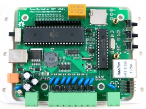
We are getting ready to release the next minor revision of OpenSprinkler DIY kit, numbered 2.2u. This revision is largely the same with the current 2.1u, with three main differences:

  1. MCU clock speed is increased to 16MHz (from 12MHz previous), by using a 16MHz crystal.
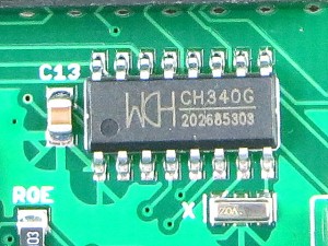
  2. Built-in USB-Serial chip is added, by using CH340G, which is a common chip in low-cost USB-serial converters.
  3. With the hardware serial chip, the bootloader is also changed to use Arduino Optiboot, at 115200 bps baud rate and a bootloader size of only 512 bytes.

IMG_0249IMG_0248

The first change above is to increase the processing speed and hopefully make the controller faster at handling complex algorithms and transferring data with the Ethernet controller. The second change above is mainly to solve the issue that it has been increasingly painful to install USBasp driver on Windows 8+. To understand the background, all of these have to do with firmware upgrade — how to reflash the microcontroller with new firmwares. Back in OpenSprinkler 2.0, I used to have a separate ATtiny45 chip on board to function as a USBtinyISP programmer, which can reflash the main MCU (ATmega644). This is not an ideal design because it involves an extra chip that we have to program; also USBtinyISP is not particularly fast. So when I designed OpenSprinkler 2.1, I made the conscious decision to get rid of ATtiny45. Instead, I decided to implement a USBasp bootloader for ATmega644, which can present the MCU itself as a USBasp programmer when a button is pressed on start-up. This is quite appealing because no extra chip is required, and the programming speed is considerably faster. The only caveat is that to use USBasp in Windows, you need to install the open-source USBasp driver. This was not the most pleasant thing to do, but wasn’t a big deal as the driver was fairly easy to install.

That is until when Windows 8 came out, with this feature called driver signature enforcement. It basically means the driver needs to be digitally signed with Microsoft, otherwise it won’t allow you to install the driver. Let’s be honest, for open-source developers, who wants to pay the big bucks to get the driver signed? So suddenly this has created an even bigger barrier for average users. The only way around the issue is to boot Windows 8 into a mode that disables driver signature enforcement. This step turns out to be unnecessarily complicated. I’ve often received comments about how it’s painful to install USBasp driver for Windows 8. I recently made a video to demonstrate how to update OpenSprinkler firmware — in this 11-minute video, 6 minutes were spent purely on explaining how to install USBasp driver for Windows 8. That’s an evidence of how unnecessarily complicated it is!

Anyways, I set out to find a better solution, and was glad that I discovered the CH340 chip. It’s basically a USB-serial chip that is often found in low-cost USB-serial cables / converters. It’s really inexpensive (less than 30 cents) and requires very few peripheral elements (just a crystal and filter caps). With this chip, you can now use the standard serial monitor to debug your program, and the bootloader can also now use the standard Arduino bootloader.

ch340g_closeup

What I like the most about this chip though, is that it does not require driver for Windows 7, 8 and above. What? Is that even possible? Yup, I’ve verified it — Windows 7, 8 and 8.1 all recognized it right away. The fact that it doesn’t require driver just makes it a whole lot easier to upgrade firmware. Windows XP and Mac OS still require driver for it, though, but that’s light years better than installing driver for Windows 8.

You may be wondering: wait a minute, what about the FT232 chip, which has been available on the standard Arduino since the beginning? Isn’t what I am trying to do here already done? Sure, CH340 is basically a replacement for FT232 — both are USB-serial converters. But there is an economic reason to go for it: even at volume quantity like 1000, FT232 costs about $3 to $4 per chip. That compared to 30 cents for CH340? You tell me. Another nice thing about CH340 is that it comes with SOIC-16 packaging, which is very easy to solder even by hand. This makes it more appealing than other low-cost alternatives like PL2303 and CP2102.

OK, I’ve done enough advertisement. I am not in any ways associated with the company that makes this chip, I am just excited, and regret that I didn’t know about it earlier 🙂
We’ve just released a new OpenSprinkler Firmware Update program, with a video tutorial to walk you through the steps of how to upgrade your firmware. Hopefully this will make it easy for users to transition to the upcoming Firmware 2.1.0, which has a number of significant new features and improvements.

The new update program is written in Qt, and does not rely on Java any more. It’s cross-platform just like before. It also supports downloading the latest firmwares from the OpenSprinkler Github repository, and auto-detect of your OpenSprinkler hardware version. If you are a Windows user (especially Windows 8 and 8.1), you will still have to go through the hassle of installing driver. The video tutorial shows you a step-by-step guide of how to install driver.

For those who are interested in modifying the OpenSprinkler firmware code, I am experimenting with CodeBender.cc, which is a cloud-based Arduino platform. It’s really convenient in that it’s essentially a web-based Arduino IDE that runs in a browser; it also make it easy for people to share their code and modifications. I think its convenience will likely lower the barrier of programming, and motivate more users to modify OpenSprinkler firmware code to add custom functionality. I’ve made requests to add OpenSprinkler to their list of supported boards. Hopefully I will hear back from them soon!

Note: check out our OpenSprinkler DC-powered version, which uses an innovative circuit design that drives sprinkler solenoids using DC-only voltage.

I often get questions about sprinkler valves, so in this post I will explain the basic electric properties of sprinkler valves. If you are designing a sprinkler controller circuit, understanding these properties can be helpful. It’s a common mistake to assume sprinkler valves work with DC voltage. While most valves indeed CAN be powered by DC voltage (see below), they are designed to work with AC voltage in the range of 22VAC to 28VAC. That’s why if you look at a standard sprinkler transformer, the output is usually AC.

The electric part of a sprinkler valve is the solenoid — it’s a cylindrical-shaped thing screwed into the valve. At the center of the solenoid is a rod supported by a spring. The solenoid has two wires connected to its internal coil. Applying 24VAC on the two wires energizes the coil, and causes the rod to contract into the solenoid. This releases the internal water pressure thus opening the valve, allowing water to flow through the valve. Removing the voltage causes the rod to revert back to its original position. This allows the water pressure to build up internally hence stopping the flow. Because closing the valve relies on internal pressure build-up, it usually takes a few seconds to completely stop the water flow. This also means if your water pressure is too low you may not be able to completely stop the water flow.

IMG_0205IMG_0206

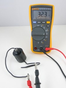
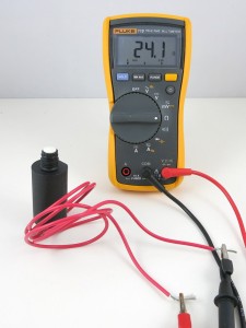
Let’s start by measuring the resistance of the sprinkler solenoid. I have two example solenoids, one made by Orbit and one made by Hunter. According to the multimeter, one measures 32.3 ohm, and the other measures 24.1 ohm. So the resistances are pretty low. If you think about it for a while, you might realize something is not quite right here: if we apply 24V on the solenoid, wouldn’t that produce a 24 V / 24.1 ohm = 1 amp current draw? That’s quite steep. In fact, my sprinkler transformer is only rated 750 mA output current, so it can’t provide enough current to drive even one solenoid?!

The catch is exactly in the fact that sprinkler solenoids are powered by AC voltage. Because the solenoid is made of a coil, it not only has coil resistance but also inductance. When operated on AC power, the inductance produces significant reactance which cannot be ignored. You can read the Wikipage to find out how reactance is calculated, but basically it has to do with the frequency of the input voltage, and the inductance of the coil. Because inductors ‘prevent’ current from changing rapidly, it behaves like a ‘resistor’ under changing current (i.e. AC). The higher the frequency, the higher the ‘resistance’ (i.e. reactance).

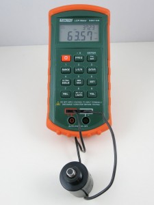
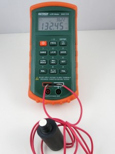
With an LCR meter, I measured the inductance of the two solenoids:
IMG_0207IMG_0209
One reads 63.57 mH, the other 132.45 mH. So if we power the solenoids by 24VAC, 60Hz, which is the standard output of a sprinkler transformer, we will get a reactance of:

This, plus the resistance, gives a total impedance of:

Note that the reactance counts into the imaginary part of the impedance. Using complex numbers is just a convenient way of denoting not only the magnitude but also the phase. For example, when you apply a sinusoid voltage on the inductor, the corresponding current is also a sinusoid wave, but with a different phase. Using complex numbers, the calculation can be carried out quite easily.

Now we can calculate the operating current under 24VAC (rms). We only care about the magnitude, so the current (rms) would be:

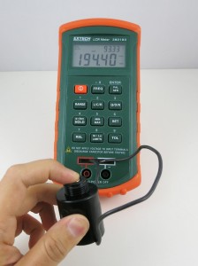
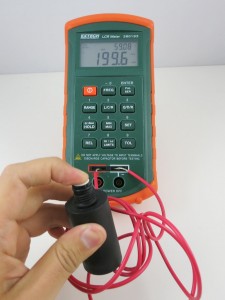
OK, so this is getting closer to the reality. But 0.6 amp current still sounds high. What is missing? Well, remember that when the solenoid is activated, the rod will be attracted into the solenoid, and that can change the inductance significantly. So let’s re-measure the inductance with the rod pushed in:

IMG_0208IMG_0210

Indeed the inductance jumped from 63.57 mH and 132.45 mH previously to 194.4 mH and 199.6 mH respectively. OK, now if we redo the calculations, we will find out that the correct reactance is:

and current (rms) os:

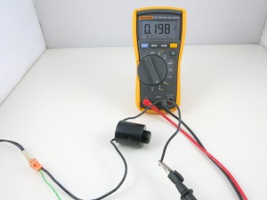
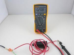
The resulting current is about the same on the Hunter solenoid. So this roughly matches the electric specification of a typical sprinkler valve. It’s actually still a bit off: if we measure the actual AC current flowing through the solenoid:
IMG_0211IMG_0212

The readings are about 0.2 amp. I suspect the difference comes from the measurement of the inductance. On my LCR meter, which can measure inductance at two frequency levels: 120 Hz and 1 kHz, I find that the inductance is measured differently under the two frequencies. Because the actual operating frequency of the solenoid is 60 Hz, and my meter cannot measure 60 Hz, the inductance I am getting is probably somewhat off. That should explain the difference between the calculation and the actual current reading.

The 0.6 amp current we calculated above probably explains the inrush current: when the solenoid is just energized, there is an impulse current that’s typically higher than the holding current. This is because the rod is still out, and hence the reactance is lower, causing a higher current than when the rod is attracted in.

Operating Sprinkler Valves Under DC

Note: check out our OpenSprinkler DC-powered version, which uses an innovative circuit design that drives sprinkler solenoids using DC-only voltage.

From the calculations above, it’s obvious that the coil inductance is important at limiting the operating current when the valve is powered under AC. What about if we power the valve under DC? Obviously we shouldn’t use 24VDC, because that would draw too much current (0.75 to 1 amp). If you search online, you will find plenty of posts talking about powering sprinkler valves using 12VDC. This actually works well in general. Using 12VDC has advantages in that 12VDC power adapters are cheaper and much easier to find; the circuit design is simpler, and you can use the same circuit to interface with other DC devices like relays and motors. In contrast, 24VAC power circuits are more complex and you can’t use the same circuit to directly interface with DC devices.

However, you should be aware that because the sprinkler solenoid’s resistance is pretty low, the operating current under 12VDC will be relatively high, around 400 to 500 mA. This more than doubles the 200 mA operating current (rms) under 24VAC. Also, the coil will heat up more, and this potentially shortens its life. For example, under 12VDC, the Orbit valve above will dissipate 12 * 12 / 32.3 = 4.5 Watt; whereas under 24VAC, the same valve only dissipates 0.2 * 0.2 * 32.3 = 1.3 Watt (note that only the resistive portion dissipate power, inductive portion does’t).

Again, the issue is that under DC there is no reactance, so the coil’s inductance plays no effect at limiting the current. What if we reduce the voltage further to 9VDC, in order to reduce the operating current? After all, the solenoid only needs 200mA holding current to remain activated. Unfortunately that won’t work: I’ve tried powering solenoids with 9V, and I can’t get the valve to reliably energize. The problem is that 9V is not sufficient to provide the required inrush current, so the rod cannot get fully attracted in. However, if the rod is already in, 9V is sufficient to hold the solenoid activated. So if you really want to make it work with 9V, you need a circuit that can provide a high impulse voltage; then once the solenoid is activated, you can lower the voltage to reduce the current (hence power) consumption. A possible solution is to use a boot converter (very much similar to circuits for latching solenoids) to provide an impulse high voltage, but this comes at the cost of increased circuit and software complexity.

Update: check out our new standalone OpenSprinkler Bee (OSBee) 2.0 with built-in WiFi and OLED display.

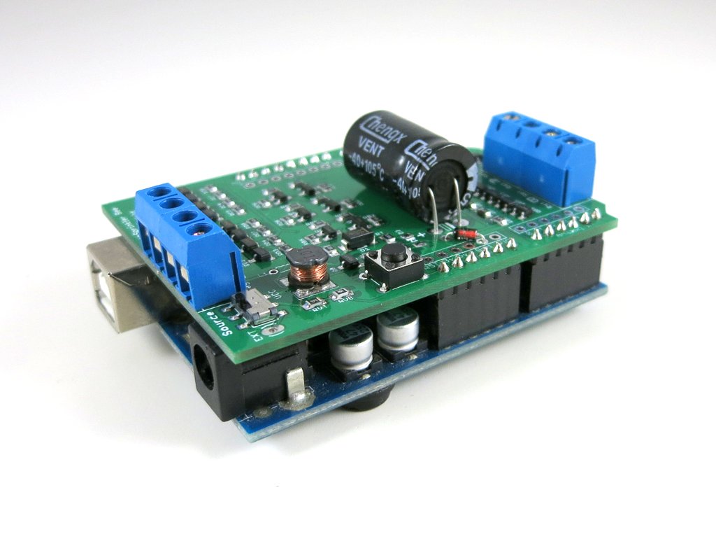
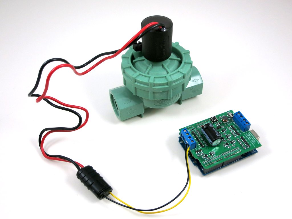
Two months ago, I wrote a blog post about the preview of OpenSprinkler Bee, which is an open-source arduino-based controller for battery-operated sprinkler valves. While that’s still in the development stage, today I am glad to announce that an Arduino shield version of OpenSprinkler Bee is completed and immediately available for purchase at the Rayshobby Shop.

Update: check out our new standalone OpenSprinkler Bee (OSBee) 2.0 with built-in WiFi and OLED display.

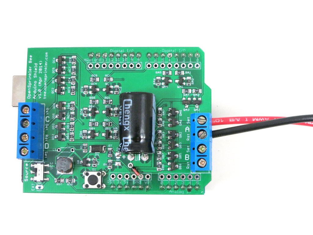
IMG_0073IMG_0075

So what is this Arduino shield version, and how is this different from other OpenSprinkler prodcuts that we carry? Well, an Arduino shield is a circuit board that you plug into an existing Arduino — it does not have a microcontroller chip itself, but contains additional circuitry that extends the basic functionality of an Arduino. So to use the shield, you will need to provide an existing Arduino board.

How is the OpenSprinkler Bee (OSBee) different from the other OpenSprinkler products? The main difference is that OSBee is designed to work with battery-operated sprinkler valves. These valves internally use a latching solenoid, which only draws power when you open or close the valve, and does not draw power if it remains in the same state. So it’s very efficient and suitable for battery-operated controllers. The other OpenSprinkler products, such as OpenSprinkler 2.1s, DIY 2.1u, OSPi 1.4, OSBo 1.0, are all designed for 24V AC sprinkler valves, which operate on 24V AC and require a power adapter / transformer.

While OSBee shield itself does not have built-in wireless modules, you can stack it with other Arduino shields, such as RF, WiFi, Ethernet shields, to provide web connectivity. The OSBee Arduino library has one example of using the Arduino Ethernet shield with OSBee shield to create a web interface for sprinkler control.

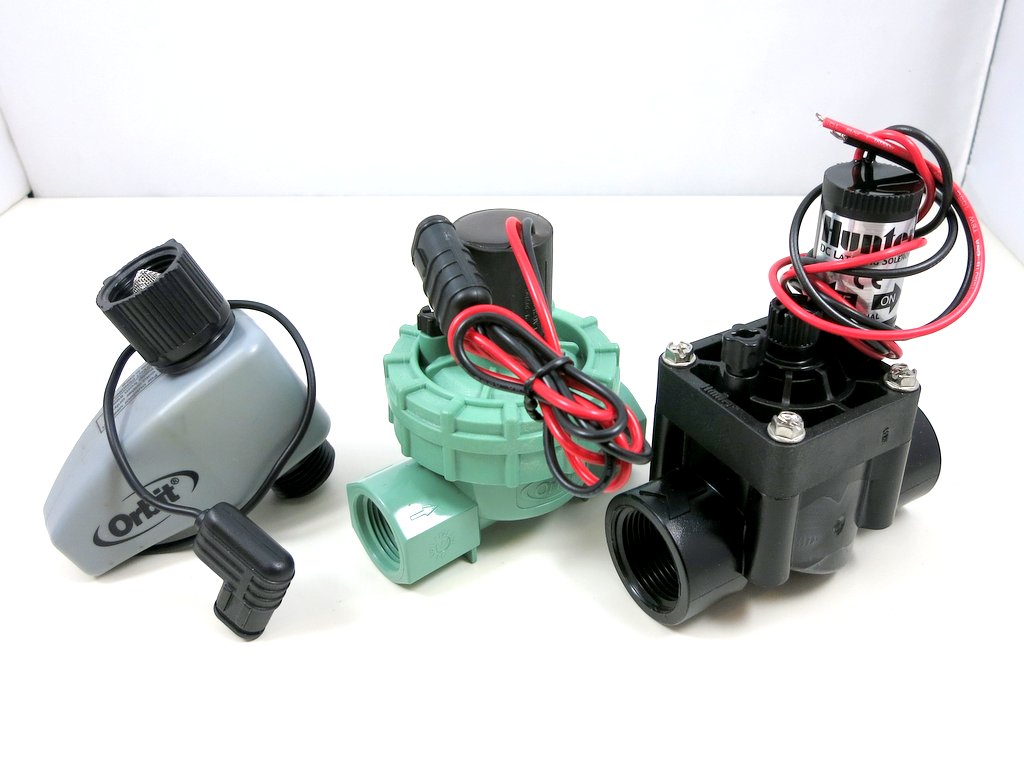
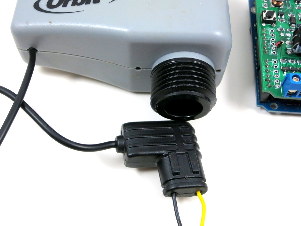
Is there any easy way to tell latching solenoid valves from 24V AC valves? Yes. Latching solenoid valves usually come with a special plug, and the two wires are usually colored differently because the solenoid has polarity. 24V AC valves usually come with just two wires colored in the same way (because AC voltage has no polarity). Here are some examples of latching solenoid valves. Note the special plugs and/or different wire colors.

IMG_0072IMG_0078

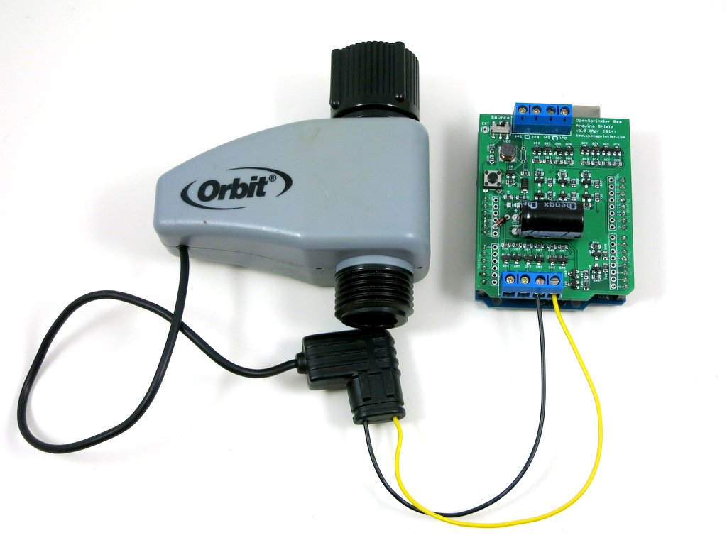
For valves that come with stripped wires, simply attach them to the screw terminal blocks on OSBee shield. For valves with special plugs, you can cut and strip two pieces of wire (20 to 24 AWG): insert one end of the wire to the plug, and the other end to the screw terminal block.

IMG_0080IMG_0077

How to open or close the latching solenoid valve? Electrically, latching solenoid valves have quite low coil resistance (a few ohms). To open the valve, you apply a momentary positive voltage on the coil. The specific voltage depends on the valve specification, but it typically varies between 9V to 22V. To close the valve, just reverse the voltage polarity. The important thing to keep in mind is that the voltage is applied as a pulse — usually 25 to 100 milliseconds. Because the coil resistance is so low, the instantaneous current is very high, up to a few amps. So you can’t apply the voltage continuously (or it will smoke the coil or the power supply!) In addition, it’s better to first build up the voltage into a capacitor, and then dump the charge to the valve from the capaictor.

How to generate such a high voltage from Arduino’s 5V or 3.3V pin? It’s by using a neat circuitry called ‘boost converter‘. The Wikipedia has plenty of information about how it works, but the basic principle is to use a MOSFET switch, an inductor, a diode, and a PWM signal to build up the charge into a capacitor. This way you can generate a high voltage from a low-voltage source such as AA batteries.

How to apply a voltage in both polarities? This is by using another neat circuitry called ‘H-Bridge‘. The H-Bridge is made of four MOSFET switches. By closing the pair of switches in each diagonal direction, you can apply voltage in either positive or negative polarity. Because you also need a state where no voltage is applied on the solenoid, that’s three states in total and hence two microcontroller pins are required to produce three states. Wait, why not directly use two microcontroller pins to apply the voltage? Well, microcontroller pins can neither handle high voltage nor provide high current, so you need MOSFETs to help switch high voltage and high current using only logic signals from the microcontroller.

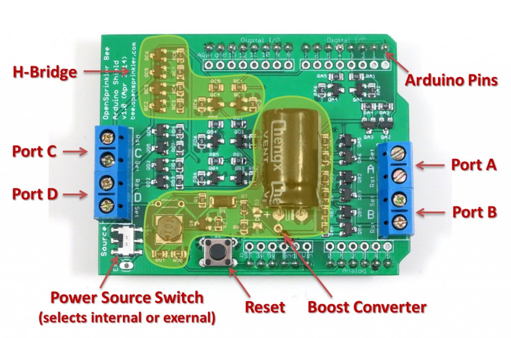
With all the technical concepts explained, here is the diagram of the various components on the OSBee Sheild:
osbee_shield_diagram

The shield can switch 4 independent valves / zones. The boosting voltage is software adjustable — anywhere from 9V to 24V. An Arduino library with three demo programs are provided in the OSBee Github repository. For details, please refer to:

OSBee Shield v1.0 is now available for purchase at the Rayshobby Shop. Thanks!

At Bay Area Maker Faire 2014

We are at the Bay Area Maker Faire at San Mateo Event Center. This year we got assigned to Station 5 (HomeGrown Village), which is a bit surprising because the past two years we’ve always been at Station 2 with the Arduino and Raspberry Pi gadgets. But this is probably an interesting change as we will be neighbors to other makers working on smart watering and home grown food. If you are at the faire, make sure to come by Station 5 and take a look at our gadgets. See you there!

IMG_0084

« Newer Posts - Older Posts »