Feed on
Posts
Comments

I just finished a batch of ordering yesterday, and felt that it would be fun to document my favorite distributors, suppliers, and PCB manufacturers. This is basically a review of some websites and stores that I regularly buy electronic components, supplies, and PCBs from. It’s suitable for buying in small to medium quantity (i.e. a few to a few hundred). When rating them, I consider a combination of factors including price, easiness of choosing parts, and shipping time and cost. Keep in mind that I am located on the east coast, so shipping cost and time may be different for you. Also, there are some negative reviews, you have been warned 🙂 Hope my comments and recommendations will be useful for other hobby makers.


Components

First of all, Octopart is a great distributor search engine. If you know the part number, you should definitely check with Octopart to compare prices across many distributors.

1. Digi-Key: one of my favorites.

  • Part selection: very easy, most components have high-quality pictures and datasheets. You can sort by price with a given quantity. Also, they have a comprehensive selection of components. Most parts I need can be found easily.
  • Shipping: inexpensive and extremely fast. They offer USPS first-class and priority shipping. If I order by 9pm EST, the order is shipped the same day, and arrives on the third day after shipping. Also, keep in mind that USPS delivers on Saturday as well. So if I missed something and need it in a hurry, I can order by 9pm EST on Thursday and still get the parts Saturday morning. For a small order (weighs 13 oz or below), I just choose USPS first-class, and that usually costs 3-4 dollars. I am basically getting the speed of Fedex 2-day service but with a fraction of the cost. Super! One of the main reasons I prefer Digi-Key.
  • Pricing: competitive for many categories: microcontrollers, capacitors, resistors, inductors, terminal blocks, just to name a few. The price can be higher than other distributors if you only buy in small quantity. However, considering the low shipping cost and fast shipping time, I would still definitely go with them for getting a few prototyping parts.
  • Customer service: excellent. I had to return an order once and it was processed quickly without hassle. Also, there were a few times that I needed to remove or add a few parts after ordering, and I was able to do these quickly through online chatting. Great customer support.
  • I use them for: getting a small quantity of prototyping parts, or buying a large quantity of microcontrollers, capacitors, resistors, inductors, terminal blocks etc.

2. Future Electronics: one of my favorites.

  • Part selection: not that easy, many components have datasheets but are missing pictures and certain information. Trying to find a part without knowing the part number can be tricky. They don’t have a comprehensive selection of components like Digi-Key, but they seem to carry a wider variety of SMT parts. You can sort by price. My suggestion is to use Digi-Key to search and find the part you want, and then check with Future Electronics to see if they have it available.
  • Shipping: very inexpensive for buying relatively large quantity, and very fast. They offer flat-rate shipping ($9 for Fedex Ground, $15 for 2-Day, and $33 for Next-Day service). No matter how many components I put in the order, the rate is the same. The package is shipped the same day if I order by 10pm EST. Very convenient.
  • Pricing: extremely competitive. This is where I find the lowest price. Often their single-item price is lower than the volume price found elsewhere. Super! I usually go with them for buying various ICs, capacitors, crystals, diodes, transistors, LCDs, IC sockets, pin headers.
  • Customer service: pretty good. They assign a customer representative for you, although it could take time to get response from them. Select parts carefully before ordering, because return can be tricky.
  • I use them for: buying a batch of ICs, capacitors, crystals, diodes, transistors, LCDs, IC sockets, pin headers.

3. AVnet
I have only used them twice, so I don’t have much to comment on.

  • Pros: competitive price, flat-rate shipping.
  • Cons: not easy to select parts. Again, it helps if you have the part number ready.

4. Arrow

  • Pros: competitive price, flat-rate shipping.
  • Cons: not easy to select parts. Customer service is problematic: one email about a return got no response.

5. Mouser

  • Pros: good price, wide range of parts.
  • Cons: shipping is expensive and unpredictable. Cut-off time for same-day shipping is much earlier compared to Digi-Key or Future, and the shipping cost always comes out higher than I expected. After a bad experience with the customer support (an email got no response in the end), I stopped using them. I know many people use Mouser for their competitive price. Frankly, if price matters, look for Future Electronics, AVnet, Arrow, or Verical. They are cheaper than Mouser and have flat-rate shipping, so you won’t get ripped off by unpredictable shipping cost.


PCB

For ordering PCBs, I highly recommend Seeed Studio Fusion PCB service. They are awesome: their service is low-cost, high-quality and fast. Yes, it’s a company located in China, so shipping can take longer time. But they process orders promptly. I usually order on Sunday evening (which is morning in Chinese time), and my order is in production the same day. Manufacturing takes 1 week, and shipping takes another week (I go with express mail options). If you don’t mind waiting for 2-3 weeks, you can get free International shipping with orders of $50 or above. If time matters, pay the extra $20-$30 to get DHL, which delivers in a week. That’s a total of two weeks to get PCBs delivered to your door. Plus, you get free DHL for orders of $500 or more. I generally use them for all PCB orders, whether prototyping quantity (i.e. 10), to batch quantity (a few hundred).

I’ve also used Advanced Circuits. They are US-based company, reliable, and extremely fast. Their price can be expensive, especially if order quantity is less than 200. I use them when I need a batch order of PCBs in a hurry and cannot wait for international shipping.


Supplies and Materials

  • Amazon: you will be amazed how many things you can get from Amazon. I get all sorts of things ranging from shipping tapes, labels, scales, to protective gloves, plastic organizers, to solder, copper board, electric wires, to cartridges, sprinkler solenoids etc. Get an Amazon Prime membership and you will receive most orders with 2-day shipping for free.
  • Techni-Tools: they have a wide range of soldering tools, solder bits, SMT soldering tools, wipes, conductive foam. Price can be expensive, but I am happy to invest on high-quality tools that I can use for a long time.
  • All-Spec: I get tweezers and all sorts of polybags, mylar bags from them. Very competitive price, and fast shipping.
  • ShippingSupply: I get most of my corrugated shipping boxes from them. Shipping cost can be a bit expensive. So buy in large quantity and stock them.
  • ULine: I get some corrugated boxes, and lots of labels from them. Good price, very fast and low-cost shipping.
  • eBay: eBay is a great place for getting things for cheap, and things that are hard to find elsewhere. Last year I bought Pogo pins, lead-free solder paste, RF transmitter modules, shipping label printer, and a bunch of home improvement store coupons on eBay.


Post-Maker Faire Update

The trip to Maker Faire Bay Area this year was a great success. This is the first time that I participated Maker Faire as a commercial maker. The two-day event was completely overwhelming to us. I was basically talking to people non-stop: showing demos, explaining technical details, outlining future plans, answering questions, and of course also accepting payments and handing out kits. It was a wonderful experience. I am really glad to have made new friends, many of them gave me generous comments, feedback, and encouragements. That’s the most fun part of the Maker Faire — connecting to people and discovering new ideas. Perhaps the only thing I felt sad about is not being able to go around and check other makers’ exhibits. We were so occupied at our own booth that I barely had any time to even get water. So tips for next time: bring a lot of water, and food too 🙂


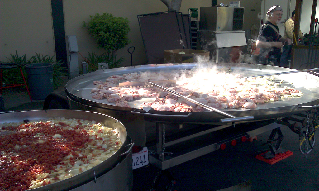
(Above: picture at the Maker Happy Hour.)

So what’s happening with OpenSprinkler since Maker Faire? Well, first of all, fulfilling orders and responding to questions have taken a lot of my time. Then, I am really trying to focus and get some time to finish the new interval scheduling program, which I see as the most flexible program that can accommodate many different scheduling need. What has been bugging me is the issue that the newly added features require a lot of program memory space, and the small 32KB flash size of ATMEGA328 doesn’t leave me much to spare. Particularly, the webpages and javascripts are currently all stored in program memory space, and I’ve been playing around to find a way to offload them to somewhere else, such as the external EEPROM. Today, a solution finally came into my mind. While searching for ‘client side include’ (CSI), I realized that it is pretty simple to include, in an html file, a javascript that is stored on a remote server. For example, using:

< script src="http://rayshobby.net/javascripts/ps1.js >< /script >

allows me to include a large javascript file that exists on a remote server and thus does not have to be stored in the microcontroller’s program space. When you access a page on OpenSprinkler, the client (i.e. your browser) will retrieve the webpage automatically upon reading that line. Ah ha, a darn simple way to offload big java scripts from the microcontroller. Why didn’t I think about it before!

Of course the problem with this approach is that if the remote server is down, you can’t really do much. The probability of this happening is usually extremely small. But still, it is a good idea to put webpages related to the most essential functions on-board, while using the remotely stored javascripts for beautifying webpages etc. In any case, this provides a good way to make the precious program memory space available for adding new features.

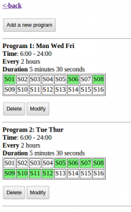
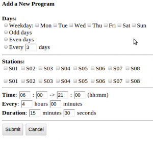
Just to give you an idea of what’s happening, here are two snapshots of the new schedule webpages I am working on:

The idea is that you can define many ‘schedule items’, each of which consists of Time (which can be a weekly schedule, odd or even day schedule, or every N day schedule), selection of stations, start time, end time, interval, and duration (down to seconds). You can add as many such items as you want, subject to the EEPROM size. These pages are not looking beautiful yet, but with the trick mentioned above, they can potentially look much more fancy.

Something else I’ve been working on is reverse engineering RF signals sent from remote temperature and humidity sensors as well as wireless rain sensors. There are lots of these off-the-shelf remote sensing transmitters that you can buy at very competitive price in retail stores. These transmitters typically work in 434 MHz RF range. I’ve found a simple method to reverse engineer their RF signals, and I’ve successfully decoded data from a temperature and humidity sensor. Hopefully I will be able to figure out the rain sensor as well. It has been great fun, and I will devote a couple of posts soon to describe how I did it.

All right, so much for today!

The initial version of the interval schedule program is now available for download in my GitHub page:
https://github.com/rayshobby/opensprinkler

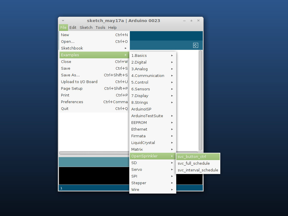
Note that all demo programs are moved to the Libraries->OpenSprinkler->examples directory. This makes it easy to load a demo program in Arduino. For example, once you put the OpenSprinkler library in your Arduino’s Libraries path, you can access a demo program by following the screenshot below:

And here is a screenshot of the interval schedule program:

Basically, it allows you to set an interval and duration for each station. In the above example, stations 1 and 2 are scheduled to be on for 20 seconds every 4 hours, stations 3 and 4 are scheduled to be on for 20 seconds every 6 hours, and the remaining four stations are scheduled to be on for 5 minutes every 50 minutes. So it’s pretty simple.

An added feature is that if more than 1 stations are scheduled to be on at the same time, they will be serialized: in other words, the controller will turn on each station one after another instead of simultaneously. The serialization is activated by setting the Multi-Station value to 0.

The program is still in a primitive state, and I am working to strengthen it so that it can support a weekly schedule. Basically, the idea is to allow the user to add any number of schedule items, where each item contains a list of selected stations, days in a week, start time, end time, interval, and duration. For example, you can specify an item like ‘schedule stations 1, 2 and 5 for every Monday and Wednesday, start at 8am and end at 6pm, turn them on for 5 minutes every 4 hours’. You can add as many schedule items as you want, or modify them later. This will make the OpenSprinkler schedule algorithm significantly more flexible and powerful. So stay tuned!

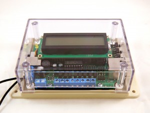
Yup, you heard it right, version 1.2u of OpenSprinkler will debut at Maker Faire Bay Area on May 19 and 20. If you are going to Maker Faire, you are welcome to drop by and see our live demos. I started working on v1.2u shortly after releasing v1.1, and we were lucky to get the PCBs and components just in time for Maker Faire. The PCBs and components are shipped directly there, so it is not yet available for online purchase until May 23. But it is available for purchase at the Maker Faire and will be available online shortly after that.

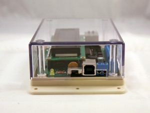
So what’s new in this version? The main improvement is an on-board USB programmer. Specifically it’s a USBtiny ISP programmer built on a pre-programmed ATtiny45. USBtiny is one among many choices to directly program an AVR microcontroller without using a bootloader. The main advantages are that it is low cost (costs just a couple of dollars) and it enables the entire program space on ATmega328 (since no bootloader is needed). It is based on a post by Tequals0 and this version makes use of the internal clock and PLL on ATtiny45 to implement USBtiny with only three external resistors. Very elegant. With the on-board USB programmer, you don’t need any external programmer any more. Note that this version is named v1.2u, where u refers to the USB connectivity.

The second change is that some components have been replaced to adopt more common parts, including the switching regulator, the Ethernet jack, and the LCD. Also, there is now a rain sensor screw terminal, and a pinout for sensing power loss. The program will be updated to support these features soon. Another change is that the LCD pin assignment is slightly modified to free up analog pin 1, which is useful for talking to sensors. Finally, the extension board connector is also updated to use more common 2×3 pin header and cable. Note that this is still compatible with the previous version of extension board. If you have the previous version of extension board, it still works with v1.2u by switching a pin on the extension cable.

If you are interested, check the detailed release notes here and the release video below.

Update: check out the RFToy — an easy-to-use standalone gadget to control remote power sockets. Also, support for remote power sockets have been added to OpenSprinkler firmware 2.1.1.

Note: the RF transmitter used in this article is available for purchase in the shop page.

In a previous post I described a way to use an Arduino to interface with remote controlled power sockets. The idea was to make use of the original remote control, and a high-side transistor switch to simulate button presses. This approach is generic: you don’t need to know how the remote control signal is encoded, instead, just treat the remote control as a black box and simulate the button presses. However, the downside of this approach is that it requires soldering wires and components to the remote control, which is quite a bit of work.

Update: check out the RFToy — an easy-to-use standalone gadget to control remote power sockets. Also, support for remote power sockets have been added to OpenSprinkler firmware 2.1.1.

Recently, inspired by the JeeLabs KAKU remote switch article, I figured out a new way to interface with these remote power switches. The method published by JeeLabs uses an RFM12B transceiver, which is cool because my OpenSprinkler design has a reserved spot for RFM12B. Unfortunately after many experiments I was unable to get it to work with my switches. However, I did succeed by using a 433MHz RF transmitter purchased from SparkFun. So below I document the process of how I did it.

To begin, I took apart the remote control. The goal is to reverse engineering the signal sent from the remote control, so that I can use an Arduino to simulate the same signal. This will allow me to use a program to control the power sockets. The schematic of the remote control circuit can be found in the previous post. Basically it consists of an encoder IC (HT2262 or PT2262) and a 433MHz RF transmitter circuit.

By connecting an oscilloscope to the circuit I was able to analyze the signal patterns. Details can be found in the video attached at the end of this post. Below are the patterns I observed when button 1 is pressed (corresponding to power socket 1).

The signal consists of two basic patterns: a short HIGH followed by a long LOW, which I call a ‘0’ all together, and a long HIGH followed by a short LOW, which I call ‘1’. The long part is roughly 500us and the short part is roughly 160us (so it’s about a 3:1 ratio). Each signal sequence consists of 25 bits: the first 16 bits are always ‘0000 1111 0101 0101’, which I call the ‘signature’; and the next 8 bits are the ‘command’, which correspond to the index of the power socket; finally, there is always an ending ‘0’.

For example, the entire sequence to toggle socket 1 is

0000 1111 0101 0101 1100 0001 0

the entire sequence for socket 2 is:

0000 1111 0101 0101 0011 0001 0

and for socket 3 it is:

0000 1111 0101 0101 0000 1101 0

Again, a ‘1’ means a 500us HIGH followed by a 160us LOW, and a ‘0’ means a 160us HIGH followed by a 500us LOW. When a button is pressed, the sequence is repeated several times, for robustness I guess.

Interestingly, you can OR the command part in order to toggle two or three sockets at the same time. For example, the sequence below will simultaneously toggle socket 1 and 2:

0000 1111 0101 0101 1111 0001 0

Next, to simulate the remote control signal using an Arduino, I used a 434MHz RF transmitter from SparkFun. This transmitter has only 4 pins: Gnd, Vcc, Antenna, and Data. The data pin can be connected to any digital pin on the Arduino in order to send the control sequence as analyzed above.

For demonstration, I used Arduino pin 10 to send the control sequence through the Data pin. The connection is as follows: VCC->+5V, GND->GND, DATA->Digital 10, ANT->a short wire. The supply voltage for the RF transmitter can be anywhere between 1.5V to 12V. The higher the voltage, the longer the transmission range. Normally 5V should be good for at least 15-20 meters. If you want the highest range, use a +12V power adapter to power your Arduino, and connect the RF transmitter Vcc pin to the Arduino VIN pin. Alternatively, you can add a voltage boost converter to bump +5V to +12V.

Below you can download the Arduino program I wrote. The code should be easy to follow.

If you have a different remote controlled power switch, you can follow the same procedure to find out the control sequence, then modify the program accordingly. A video demo is provided below:

Credits: the method is based on JeeLabs KAKU remote switch and the code is based on the kaku_demo sketch included in their RF12 Arduino library.

Note: the RF transmitter (434MHz) is available for purchase in the shop page.


Update 1: apparently if you look at the datasheet of PT2262, which I found a copy here, it explains how the encoding pattern is computed. The ‘signature’ part has to do with the status of each pin from A0 to A7 on PT2262 – whether the pin is connected to GND, VCC, or floating, and the ‘command’ part is determined by the status of each pin from D0 to D3. I compared the circuit with the datasheet and verified that the pattern I observed from the oscilloscope matches the calculation. Also, according to the datasheet and the resistor value I found on the remote control, it looks like the long delay should be about 400us and short delay 133us, which is a bit different from the 500us and 160us observed from the oscilloscope. Also, the ending ‘0’ in my sequence turns out to be a ‘sync’ bit, which is 133us high followed by 4200us low. The fact that my original sketch has worked means there is a some level of tolerance in the timings. So they do not have to be highly accurate.

Update 2: new version of remote control. A reader of this post, Chuck, sent me a question that the sketch doesn’t seem to work with his remote control. After researching this issue, we found that the new version of the remote has changed to use SMT components and also has changed the coding pattern. Chuck sent me an image of the back of the PCB. From the image and the datasheet of PT2262, I figured out the new coding pattern. Basically, the ‘signature’ part of the code has been changed from

0000 1111 0101 0101

to

1101 0111 0101 0101

More technically, the coding pattern can be derived from the connections of Pins 0-7 of PT2262. In the newer version (from the PCB image on the left), the first 4 pins are connected as HIGH, FLOAT, FLOAT, HIGH, whereas the older version is connected as LOW, LOW, HIGH, HIGH. Here HIGH means connected to Vcc, LOW means connected to Ground, FLOAT means unconnected. Taking a look at the datasheet, you can easily figure out the actual code: LOW -> 00, HIGH -> 11, FLOAT: 01.

Chuck sent me his modified code, which you can download here.


« Newer Posts - Older Posts »