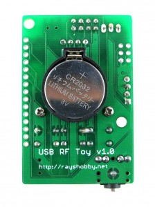
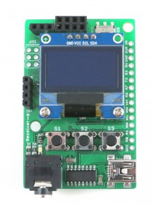
Today I am introducing the first version of RFToy — an Arduino-compatible gadget for interfacing with Radio Frequency (RF) modules. First, let me show you a few pictures of RFToy and a video introduction:
RFToy is available for purchase at Rayshobby Store.
Features
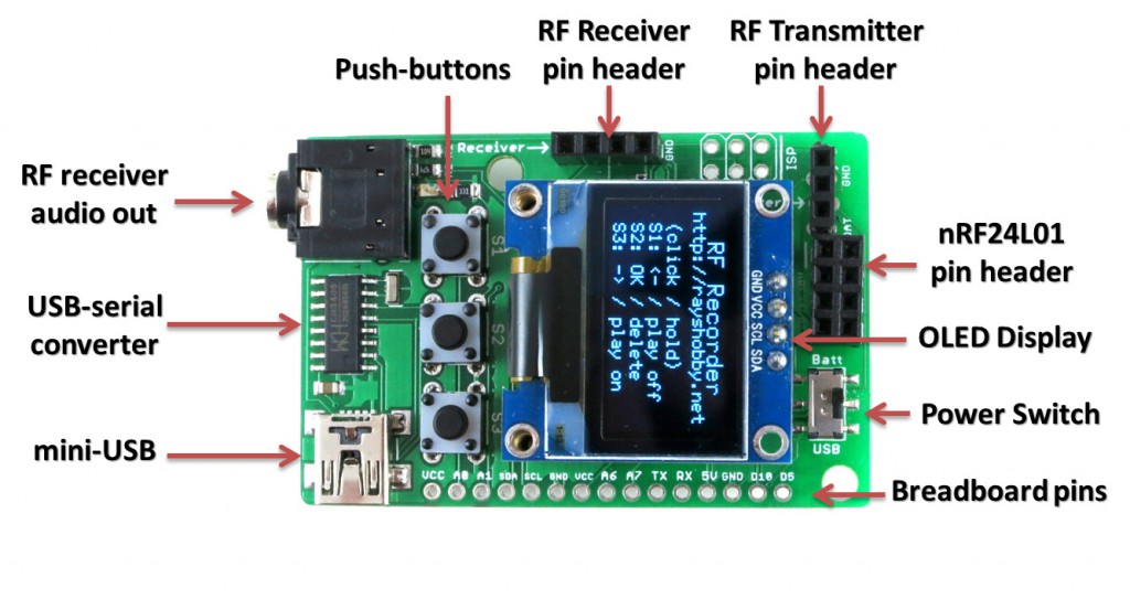
- ATmega328p @ 3.3V, 8MHz, with CH340G USB-serial converter and Arduino bootloader.
- Programming in Arduino using the on-board mini-USB port.
- One 128×64 OLED display, three tactile buttons.
- 20mm coin battery holder, and slide switch to select between USB or battery power.
- Pin headers for plugging in 433/315 MHz RF transmitter and receiver modules, and MOSFET power switches for them.
- 3.5mm audio jack to output receiver signals to a computer’s line-in port, to monitor RF waves.
- Pin headers for plugging in nRF24L01 transceiver.
- Pin headers for connecting external components and/or breadboard experiments.
So in essence, RFToy is a 8MHz Arduino with buttons, OLED display, battery holder. It’s compact (1.5″ x 2.3″) and it’s suitable for a variety of projects involving RF modules.
Demos
As shown in the video above, I’ve written a couple of examples to demonstrate the basic features of the RFToy.
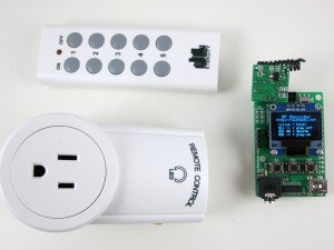
- RF Recorder: this demo shows how to use RFToy to decode signals from the remote control of a typical wireless power socket, store the decoded signal in EEPROM, and play it back to simulate the remote control. You can store up to 7 different signals, allowing you to control up to 7 power sockets. The demo is based on the RCSwitch library, and it has a basic UI using the OLED display and buttons.
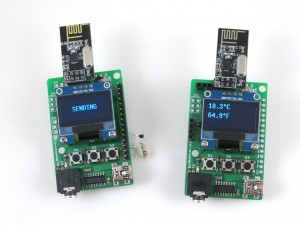
- Wireless Temperature Sensor: this demo uses a pair of RFToys — one RFToy has a thermistor (connected to analog pin A1) and sends out the temperature reading periodically through its 433MHz transmitter; the other has a 433MHz receiver, and displays the received value to the OLED. This demo is based on the VirtualWire library, and uses the watchdog timer and power-down sleep to save battery life when the sensor is not transmitting data. A variant of this demo is also provided using a pair of nRF24L01 transceivers and the Mirf library.
- Interfacing with Off-the-Shelf Wireless Sensors: previously I’ve written several blog posts about using Arduino to interface with off-the-shelf wireless temperature, humidity, rain, and soil moisture sensors. Since these sensors all work in the 433MHz frequency band, these demos can all run on RFToy, with sensor values displayed onto the OLED.
With the built-in buttons, display, and Arduino compatibility, there are tons of other projects you can build with RFToy.
User Manual
RFToy is open-source. You can check out its Arduino library code at http://github.com/rayshobby/rftoy, and hardware design files at http://github.com/rayshobby/rftoy-hw. Some technical details are provided below:
Note: the content on this page is published under Creative Commons Attribution-ShareALike (CC BY-SA) 3.0 License. Content reuse is allowed. If you have a project/product based on RFToy, please acknowledge my contribution. The software code and hardware design are published for educational purpose.
This is so awesome Ray, well done!! 🙂
How useful that it has an nRF24L01 header on it. I’ve often been somewhat annoyed that the otherwise-useful module has an awkward pinout, making it impossible to use on a breadboard or similar.
[…] has created RFToy, a simple gadget to aid in setting up wireless systems with a variety of common radio modules. […]
is RFtoy mesh network capable?
great tinkering btw!
That depends on if there is a mesh network library for nRF24L01. I think I’ve seen it somewhere. You can google to find more information.
Ray, awesome job. Out of curiosity what is the operation temperature range for the device? Could it and the OLED survive -20c?
I honestly don’t know and haven’t tested.
[…] I sawthis post at Hackaday refering to a RFToy, a cool gadget from that might be useful when working with different RF modules out there. Might be […]
nice toy to test all RF messages in the wild, Ray
for the mind sake of your mac users, please download the driver for CH340G USB-to-Serial converter at: http://goo.gl/EmN4IH (with the fix with the space inside the name of the usb com) to replace yours.
If running on Yosemite, please follow the tip to avoid strict checking of kernel extension.
More explanations here : http://arduino.stackexchange.com/questions/3700/rename-device-name-ch340-usb-to-serial-mac-os
Thanks for the pointers. These have been included in the RFtoy user manual (http://rayshobby.net/docs/rftoy_manual.pdf).
Hi,
If you want a “poor mans 2.4GHz scanner” running on your RFToy, you can find some info here: http://weatherhelge.wordpress.com/2014/12/31/2-4ghz-scanner-using-rftoy/
Cool, very nice. Thank you for sharing!
[…] To help with the first part, verifying that the sender is actually sending, I’ve combined RFToy with poor mans 2.4GHz scanner. I now have a battery driven device that can be used to see if my […]
Thanks to create RFtoy.
I’ve two questions:
1.- Why RFtoy works properly if MISO, MOSI and SCK pinout is not the “official” Arduino SPI pinout? Now I want to use a CC1101 and I wonder if it’s necessary to edit SPI.h library.
2.- If I use D10 pin to connect a DHT22 data, the system doesn’t works. It’s any incompatibility?
Thanks!!
1. I am not sure what you mean. Which pinout are you referring to? There is a 2×3 pinout for ISP programming (which we use to flash the bootloader), and there is a 2×4 pinout for nF24 module (which also uses the SPI interface.
2. Pin D10 should be set as a digital OUTPUT pin, because it’s the hardware SPI enable (SS) pin and it should remain an output pin. Please use a different pin to interface with DHT22.
Hi Ray. Thanks for your answer (it seems missing!!).
1)My first question was about JP5 header (ISP interface with NRF24L01):
In MIRF arduino official:
Pins:
MISO -> 12
MOSI -> 11
SCK -> 13
Configurable:
CE -> 8
CSN -> 7
In RFToy_JP5 header:
Pins:
MISO -> 16
MOSI -> 15
SCK -> 17
CSN -> 25
CE -> 26
IRQ -> N.C.?
Configurable:
cePin=17; software config.
csnPin=16; software config.
It’s all OK? because official Mirf hasn’t the same pinout than RFToy.
2) Second question (D10):
Then, when ISP is used, D10 has to be not used?
Thanks again!!
Very good product.
With CC1101 modules (elechouse, for example), it necessary to connect SPI_GO02 with one of RFToy pins? IRQ pin maybe? (in this case a extra wire is needed).
I have my RFToy and have no problems getting it to record signals, but I seem to be having some issues sending the data once captured. I have tried several outlets and even with less than 12 inches between RFToy and the outlet, it doesn’t seem to be working.
Do you have an antenna soldered to the transmitter? Sometimes long antennas actually have a negative impact. Try to shorten the antenna. It’s also possible that the transmitter might be defective and not working, in which case we can provide a replacement.
Nope. It’s all stock. I’m familiar with tuning antennas to specific freq’s so I haven’t messed with it.
I have a windows blind that is currently controlled by a RF remote (the spec says it uses RF freq 2.4 GHz).
I was hoping to use the RFToy with nRF24L01 to capture the RF code and do some automation around it.
I noticed that the RFToy is not detecting the RF signal. I am sure I am missing something here. Anyone has any experience automating Window Blinds using RFToy ?
Anybody who can tell if these are able to connect to somfy rollerblinds out off the box?. mine is using the 433MHz, but i know it is not always that easy to connect to all 433MHz products.
Depends on how the rollerblind signals are encoded. You probably want to use RFToy to sniff the signal first to check how the signals are encoded.
Great stuff. Is it possible to sniff 933mhz? Have an alarm system with door sensors operating in 9xx MHz range. If you had 933 receiver plugged in, would it work with rf toy?
Yes, if you plug in a 933MHz receiver you should be able to sniff the signal. If the encoding matches what RC-Switch library can decode, it should be able to identify the signal immediately. Otherwise you may have to manually check the sniffed signal and find out the decoding pattern.
When a CC1101 module is connected (elechouse, for example), is it necessary to get GO02 pin connected to any RFToy pin? …the IRQ pin is the answer? (in this case, a extra wire is needed).
What is the maximum output current for the extra analog pins? I’d like to drive a small speaker.
I think you mean the PWM pins (digital pins that can output PWM signals). On Arduino the maximum output current is generally around 40mA.
Thanks!
I’m having some trouble driving simple buzzers and LEDs with the digital breadboard pins (D3 (pin 1), D10 (pin 14)) and reading with the analog pins (A1 (pin 24)). When I write the pins high using the Blink Arduino example, voltage is still zero when measured with the multimeter. Is there an additional step that is necessary with the RFToy? I’m having no problems blinking the internal LED (pin 13).
I don’t understand what you mean by D1 (pin 1), D10 (pin 14) — what is pin 1 and pin 14?
Hi,
After 3 days of successful experiments, today my RFTOY failed.
Having trouble uploading sketch to board.
stk500_recv(): programmer is not responding
Also when powering on dont see activity on LED SCK and OLED doesnt turns on.
Could be bootloader broken ?
Thank you.
It’s possible that the microUSB jack has got disconnected. Can you check the microUSB connector and see if there is any visible damage?
Thank you for ur reply.
Problem solved. I somehow fried CH340 and it was mangling TX/RX pins during boot.
Soldered ISP pins and flashed with Avrisp. Kinda inconvinient but … will order some CH chips.
By the way ISP pins are reversed on your PCB 😀
Thank you one more time. You have awesome products.
Ray,
This has been a really great product, however I broke the i2c oled screen. Could you point to me which one to purchase as replacement?
Thank you,
Ulises.
It’s an I2C OLED display (the chip number is SSD1306).
Hi,
I am looking for a tool to remote control my garage door and window roller shutters (898Mhz, rolling codes)
Could this be used for that? Where could I find 868 modules?
Thanks
Gabor
Rolling code requires proprietary encoding chip. They are not publicly available. Only the manufacturers have them.
Just received my RFToy. Maybe a stupid question but is an antenna required to be soldered onto the receiver and transmitter for it to work? I had a very quick play out of the box and was not able to sniff any signals.
Antenna is not required. What’s the brand name and model number of your RF socket? It may be that it’s using a protocol not supported by the built-in firmware of RFToy. But there are some work-arounds.
I’m using the Arlec RC13 (http://www.arlec.com.au/wp-content/files/RC13.pdf)
OK, I am not familiar with this brand. Do you have Etekcity brand? That should work well with RFtoy.
I can’t see that Etekcity produce an Australian socket. Searching online I can see a product (also called RC-13) from Digoo, any experience with that? Another product found is Doss MRC03V2. Struggling to find anything else…
Hi Ray,
I was going to order two of the RFToy 1.0 (classic) until I saw the 3.0 now available. Now I’m not sure which version to get. Is there a video that you go over the differences between the two versions (i.e. pro/con [if any])? Does V1.0 work with V3.0?
Also, what shipping options are there to Canada? Do you have ground as in USPS?
Regards
The main differences are that 1.0 does not have WiFi, but supports nRF24L01 transceiver, in addition to 433/315Mhz RF transmitter/receiver pairs. In contrast 3.0 supports WiFi, but does not support nRF24L01.
Hi i want to create a network of sharing their location and identity information among devices so can I do it????
Cool project! I want DIY a rftoy and I have a question .Is the crystal oscillator on the board 8 MHz?