Feed on
Posts
Comments

It’s hard to believe that two years have gone by since my last post. Lots of things happened during these two years: on the good side, we have our first baby born during a year of pandemic, and he is bringing joy to the family every day. On the bad side, there is a pandemic, which brought so many challenges, from supply chain issues to shipping delays and to the difficulty of finding available employees to hire. The pandemic has also taken a huge roll on my mental health, significantly limiting my productivity and creativity.

This post is my attempt to resume regular blogging, a habit that I’ve always enjoyed in the past but was lost during the two terrible years. I am hoping this will motivate me to continue learning and sharing new knowledge about electronics, and continue to provide new passion in my life.


In this post, I will briefly summarize I/O expander choices I’ve considered when designing the OpenSprinkler circuits, and the pros and cons of each choice. I/O expanders are often necessary when the microcontroller’s I/O pins are insufficient for the application. For example, a sprinkler controller may need a large number of output pins in order to drive many zones independently. This is the reason that from the very first version of OpenSprinkler, I’ve decided to use an output expander, to allows the number of zones to be scalable and not limited by the available I/O pins on the microcontroller itself.

74HC595 Shift Register

The most common choice for increasing output pins is to use a 74HC595 shift register, or more precisely: serial-in, parallel-out shift register. 74HC595 is cheap, widely available, and quite simple to connect to a microcontroller like Arduino. Each chip adds 8 output pins, and you can daisy chain them to almost any number, limited only by the potential signal degradation/distortion when cascading too many of them. At the minimum, a microcontroller only needs to use 3 pins to interface with any number of daisy chained shift registers. These pins are named LATCH, CLOCK, and DATA, which are essentially CS, CLOCK, and MOSI pins in SPI terms. You can begin the data transfer by setting LATCH pin low, then at the rising edge of each CLOCK cycle, the HIGH or LOW signal presented on the DATA pin is transferred to the first storage register, while the data already transferred in previous clock cycles are shifted down to the next storage registers respectively, hence the name ‘shift register’. After 8 clock cycles, 8 bits of data are shifted in. Finally set the LATCH pin high, upon which the values in the storage registers are transferred and presented on the output buffers. You can bit bang the pin values, use Arduino’s built-in shiftOut function, or if CLOCK and DATA pins happen to be connected to the microcontroller’s SPI CLK and MOSI pins, you can use SPI functions for even faster operation.

One advantage of 74HC595 is that it has a separate set of storage registers vs. output latches (aka output buffers). During data transfer, this allows the output values remain stable and not affected by the data that’s being shifted in. The output values only update upon the rising edge of the LATCH pin. This compares favorably to other shift registers like 74HC164 that are even cheaper but don’t have output latches (thus the output values may flicker during data transfer and such the flickering would be problematic for output devices like sprinkler solenoids).

Pros:

  • Very cheap (a couple of cents in bulk pricing) and widely available.
  • Can be daisy chained to enable a large number of output pins
  • Relatively small number of microcontroller pins required to interface with it.

While the list of pros makes it sound like this is the perfect choice for almost any application, there are also a number of cons which are somewhat subtle but important for sprinkler controllers.

Cons:

  • 74HC595 is output only, it does not support input pins (for that there are dedicated parallel-in, serial out shift registers, basically the opposite of 74HC595).
  • Maximum output current is small — according to the datasheet, each output pin can only source or sink up to 4~7mA, depending on the supply voltage. If the output device is a transistor or MOSFET, this is more than sufficient. But on AC-powered OpenSprinkler, the output device is a traic, such as MAC97 or Z0103MN, which require relatively large gate current, and 4~7mA is only barely enough.
  • Upon powering up, the output states are not deterministic — this means if LEDs are connected as output devices, they may have a brief moment of flickering upon powering up; similarly if the output devices are solenoid drivers like traics, some solenoids may be momentarily activated until the microcontroller clears out the output buffer. This problem can be alleviated by using an additional pin — the output enable pin — to disable the output latches upon powering up, but the downside is this requires another microcontroller pin.
  • The communication between microcontroller and shift register is one-way, so it’s difficult for the microcontroller to detect or enumerate how many shift registers are connected. On OpenSprinkler, I had to use an analog pin in conjunction with a parallel resistor per shift register to be able to detect/enumerate the number of shift registers. This is a downside, particularly if the microcontroller is short of analog pins.

I2C I/O Expanders (such as PCF8574/8575/PCA9555/9535)

Due to the advantages of 74HC595, I used it on the legacy versions of OpenSprinkler (1.x and 2.x) for many years, until I had to move on to switch the microcontroller to ESP8266, in order to support built-in WiFi. Suddenly the cons of 74HC595 became a show stopper, partly because ESP8266 has a much smaller number of GPIO pins, so I could not afford to spare many GPIO pins to interface with 74HC595; and partly because ESP8266 has only one analog pin, which has to be used for solenoid current sensing, thus cannot be used to detect/enumerate the number of expanders.

This is where I discovered there are a large family of I2C I/O expanders. In fact NXP has a document that nicely summarizes the various choices. Most of them differ by the number of I/O pins available, output type, maximum output current, the availability of pull-up resistors on each pin. The output type is quite interesting: some of them use push-pull (i.e. Totem-poll) which means they can both source and sink a large amount of current (i.e. strong current sources and sinks); some of them (e.g. Quasi-output) can sink a large amount of current but only source a small amount of current (i.e. strong sinks but weak sources); some of them (e.g. open-drain) can only sink current but not source current at all.

Most of the pros and cons below are exactly the counterparts of the cons and pros of 74HC595 respectively.

Pros:

  • Each pin can be configured as either input or output, so with a single I/O expander chip, some of the pins can be configured as outputs to drive triacs or MOSFETs; while others can be configured as inputs to read sensor values or button statues.
  • All of them interface with the microcontroller through I2C, therefore they require only the SDA and SCL pins from the microcontroller, and the same two pins can be shared with other I2C devices such as real-time clock, OLED display etc. This is particularly suitable for ESP8266, on which the number of GPIO pins are very limited.
  • Using I2C almost means the communication is bidirectional — the microcontroller can detect and enumerate the number of I/O expanders connected to it.
  • Another advantage of I2C is that each I/O expander has a unique I2C address, so by carefully allocating the address of each expander, the microcontroller can detect which type of OpenSprinkler (AC-powered, DC-powered, or Latch) by reading the I2C address.
  • The I/O pins on these expanders can source or sink a large amount of current (up to 25mA), which is more than sufficient to drive triacs. Well, not all of them though: when designing OpenSprinkler 3.0, I was only aware of PCF8574 and PCF8575, which are weak current sources, so they have to be combined with PNP transistors or P-ch MOSFETs to source a large number of current. By the time I started designing OpenSprinkler 3.1 and 3.2, I became aware of PCA9555 and PCA9535 — they are strong current sources so there is no longer need for additional transistors or MOSFETs.
  • Upon powering up, the output states are deterministic — in fact, the outputs are always high upon powering up, with weak pull-up resistors. This makes it possible to overcome the flickering issue at powering up.

Cons:

  • They are relatively expansive (a dollar or so in bulk pricing). While this may not seem much, it does stand out quite significantly when compared to the pricing of 74HC595. Also, the chip shortage caused by the pandemic has made them even more expensive and frequently out of stock. In contrast, it hasn’t affected the pricing or availability of 74HC595 much.
  • Because each expander must have a unique I2C address, and each chip (e.g. PCA9555) only has 3 bits of address pins, this means you can only connect up to 8 expanders chips. This is also a disadvantage compared to 74HC595 where you can daisy chain virtually unlimited number of expanders. Despite this limitation, I decided this is a worthwhile compromise to make for OpenSprinkler as the total number of zones per controller is usually not that much.

Among all the I2C expander chips, PCF8574/8575/PCA9555/9535 are relatively more common and available. The differences between them are:

  • PCF8574 has 8 I/O pins, and PCF8575 has 16. Both of them are of Quasi-output type, so they can sink but not source a large amount of current. They were used for OpenSprinkler 3.0 controller and zone expanders.
  • PCA9555 and PCA9535 both have 16 I/O pins, and both use Totem-poll output, so they can both sink and source a large amount of current. They are used in the current OpenSprinkler 3.2 controller and zone expanders. The only difference between the two is that PCA9555 has built-in pull-up resistor while PCA9535 does not. Thus for any pin configured as input, PCA9535 requires an external pull-up resistor.

CH423s I2C I/O expander

Recently I discovered a very low-cost I2C I/O expander CH423s. It’s made by a Chinese company QinHeng which is famous for making the low-cost USB-serial chip CH340. CH423s has a bulk pricing of about 20 cents, and it has 16 output only pins with 8 additional input/output pins. So it’s a quite capable and versatile chip. However, after reading its datasheet and understanding the sample programs, I found it has a big downside, that is it takes over too many I2C addresses. This is a quite strange design of the chip — unlike PCA9555/PCA9535 (each of which only takes over one I2C address, and you can configure the input/output of each pin by settings configuration registers), CH423s uses multiple I2C addresses to eliminate the need of configuration registers. While it is relatively easy to program, the large span of I2C address space makes it infeasible when the same I2C bus has to be shared with other devices like real-time clock and OLED display, which may conflict with its address space. Also, there are not configuration bits for the I2C address, so it’s not possible to use it on zone expanders. Nonetheless, this is an interesting choice to consider for some applications, if the I2C address space is not a problem.


1-Wire I/O expanders (DS2413/DS2408)

Wouldn’t it be nice if the microcontroller only needs one-pin to communicate with I/O expanders? It turns out such an option does exist! Take a look at the 1-Wire I/O expander chips: DS2413 supports two I/O pins, and DS2408 supports 8 I/O pins. They interface with a microcontroller through a single data wire, hence the name 1-wire. Probably the most well-known 1-wire device is the DS18B20 temperature sensor. While this may not seem a lot of I/O pins, each chip actually has a globally unique address, so you can connect virtually unlimited number of these chips, all sharing a single data line! These chips were brought to my attention by Patrick Morse — he proposed this as a solution to implement Hunter’s EZ Decode system. In fact, before his email, I’ve from time to time received requests to develop a 2-wire decoder system — similar to I2C, 2-wire decoders use a clock line and data line to transfer signals between the microcontroller and the solenoid driver. This is an attractive solution for applications where it’s a hassle to install a large number of long copper wires between the sprinkler controller and each solenoid. 2-wire decoders solve the problem by connecting all solenoid serially using only 2 data lines. Each decoder would have a unique address just like in the case of I2C. The microcontroller sends commands to discover the unique address of each decoder connected on the bus, and consequently can switch each solenoid valve independently. The 1-wire decoder would be a further simplification by reducing one data wire. The commercially available 2-wire decoders generally use proprietary communication protocols that are not open-sourced. The existence of DS2413 and DS2408 means we can easily implement a 1-wire decoder using well-documented 1-wire protocol. That’s great!

Pros:

  • Using one single data line, suitable for implementing 1-wire decoders that can significantly save the amount of copper wires required in a sprinkler system.
  • Each chip has a globally unique 1-wire address, making it possible to connect a large number of chips all sharing the same data line. By detecting the 1-wire address, the microcontroller can detect and enumerate each chip.

Cons:

  • Relatively expensive: DS2413 has a bulk pricing of close to 2 dollars, and it only supports 2 I/O pins. Also they are less commonly used so more prone to chip shortage issues.

While it’s possible to interface with these devices by directly using a microcontroller pin (through the open-source 1-wire library), it may be better to use a 1-wire master chip, which interface with the microcontroller through I2C and it can talk to 1-wire devices using a more robust data line. The 1-wire master chip is particularly useful for ESP8266, which doesn’t have many GPIOs, so it may be necessary to delegate the communication task to a separate chip.


To conclude, this posts summarizes some of the I/O expander options I’ve considered when designing OpenSprinkler circuits, and the pros and cons of each. In the case of OpenSprinkler 3.x, the design decisions were largely driven by the limited number of pins on ESP8266. With other microcontrollers that are not short of GPIO pins, 74HC595 may still be the most attractive choice due to its many advantages and the significantly lower cost.
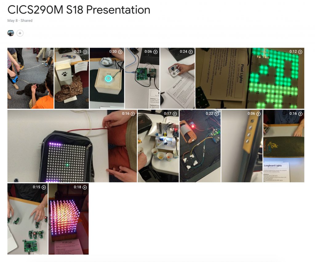
Can’t believe I have been silent on this blog for more than a year now. I would really like to get back to blogging more regularly, and hopefully this post serves as a good starting point. As the first order of business, I would like to showcase a number of student projects from a new class I taught at UMass in the Spring 2018 semester. It’s a brand-new class called Make — A Hands-on Introduction to Physical Computing. It covers basic electronics, circuits, Arduino programming, sensors, actuators, ESP8266, Processing, and rapid prototyping techniques. It’s a rather exciting adventure for me, as it’s the first time this course has ever been offered in my college, and it fulfills the college’s lab science credit. I have both the freedom to choose whatever topics I am passionate about teaching the students, and the burden of designing the complete set of lectures, weekly lab, homework, and exam.

The class ended with a final project where students work in two-person teams for 6 weeks to complete a project of their choice. The basic requirement is that it must be a physical computing project that involves both constructing hardware and developing software. The outcome was really satisfying as many of the projects are truly impressive and/or innovative. It’s particularly so as for many students this was the first time they have ever learned about electronics and Arduino. Below I briefly describe some of my favorite projects. I took videos of some projects, which you can find in this shared Google Photos album. The complete list of 27 project can be found in this folder of Google sites (I asked every team to create a Google site to document their project).

The most ambitious and visually marvelous project is the 8x8x8 Neopixel Cube project by Alex and Chris (warning, the site is loaded with pictures and videos so loads rather slowly). Though there is an abundance of LED cube projects you can find online, this one is based on Neopixels, so it’s a full-color LED cube and it’s slightly easier to solder than standard color LEDs. They’ve done a fantastic job constructing the cube, and solved a number engineering challenges such as power stability issues, and data transfer speed issues by splitting the cube into sections and providing data entry point for each section separately using the FastLED library. I have a video clip showing the project in action. I wish I had taken a longer video because there were a few really cool animations (e.g. visualizing 3D surfaces, video streaming, 3D snake game) that show off just how amazing a Neopixel cube is.

Then there is a smart mirror project, ironically called Dumb Mirror, by Sam. It’s constructed using a two-way mirror, with a Raspberry Pi driving a scavenged LCD display and a Neopixel ring. A Python program grabs time, news, and weather information and displays them to the LCD screen. There are also some buttons on the side for user interaction. I’ve two short video clips (video1 and video2) showing the project in action. It’s aesthetically beautiful and quite functional as well, makes me want to own one myself.

Next in line is the Mint Drawing Tin project by Paul. This is a really cute project constructed using an Arduino nano, 128×64 OLED display, buttons, Lithium battery, and a 3D printed front panel, snugly fit inside a Altoids tin. It’s like a mini version of Etch a Sketch, but much cooler as it can store image frames and play them back as an animation. I have a thing for mint-tin project, as my own journey of Making began many years ago with a mint-tin sprinkler controller.

Some students made custom PCBs for their projects. One of them is the PixelLight project by Julian. It’s constructed by many Neopixel tiles daisy-chained to make a larger display. Each tile is a custom PCB of 10cmx10cm in size containing 4 Neopixels. The original goal was that the user can connect the tiles in an arbitrary manner and the system can automatically identify the topology of the connections. That proved to be a bit of a challenge so in the end he settled with a pre-determined topology. Still, it’s a quite elegant and visually pleasing project, and the display patterns can be changed in dynamically in real-time by using a ESP8266-based microcontroller and the Blynk app.

Another custom PCB project is the Radio Fireflies by Nick and Emily. It simulates how fireflies in nature synchronize their flashing patterns. Each node is a custom-made circuit consisting of an ATtiny85 mcu, color LED, 433MHz RF transmitter and receiver, and buzzer. RF is used to simulate how individual fireflies communicate with each other, eventually leading to synchronized flashing pattern. It’s a cool and ambitious project, though the real-time demo didn’t work very well as the presentation room was full of RF interferences.

A really fun and entertaining project is the Voice-Controlled Pong by Mike and Garret. It’s made of an Arduino, a 16×16 Neopixel matrix, and two microphone sensors. Each of the two players uses their voice to control the movement of the bat, i.e. the louder the sound the higher the bat moves. At first, it looks somewhat silly that the two players just keep yelling ‘Ahhhh’ repeatedly towards the microphone sensors, but when you try it out yourself, you will find it’s absolutely a joyful and entertaining game to play.

And of course there has to be a pet-centered project. The Bone Appétit is a lovely project by Mary and Nick, perfect for pet owners — it’s made of a Raspberry Pi, camera, servo, load cell (for measuring food weight), tucked inside a lovely wooden box. Using a Blynk app, they can monitor the pet, release food up to a pre-defined weight, and snap a picture. The best part of their demonstration is that they brought an actual puppy, who must have had a great time drawing so much attention from the audience.

There are a number of other amazing projects, like color candy sorter, pocket synthesizer, smart curtain, mail checker, pellet stove monitor, secret knock door lock etc. It’s truly delightful and rewarding to see such a range of creative student projects. I am teaching the Make course a second time this semester and will update the post when this semester’s final presentation ends.


Content

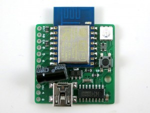
ESP8266 — a very low-cost and flexible Serial-to-WiFi module that has gained a lot of popularity recently. It allows any microcontroller to have WiFi capability by simply using serial communication. In a previous blog post, I demonstrated how to use ESP8266 combined with an Arduino to set up a very simple web server. This time I built a standalone gadget for prototyping called the ESP8266 Toy (or ESPToy for short). There is also a more serious web server demo in the end that shows how to serve HTML files from a SD card, and using JSON and AJAX to implement prettier web design.

You should also know that there has been a lot of on-going development for this module. For example, there is a Lua-based firmware for ESP8266, which is quite amazing. Also check out the community forum here.

As usual, a video demo first:

New ESPToy 1.2:

Original ESPToy 1.0/1.1: Youtube Video Link


ESP8266 module and ESP8266 Toy are available for purchase at Rayshobby Store.


Features

New ESPToy 1.2:

  • ESP-12 SMD WiFi module, pre-flashed with Lua firmware and a startup demo script.
  • 3.3V 250mA linear regulator.
  • Programming using the on-board mini-USB port.
  • One color (RGB) LED, one pushbutton (used as a general-purpose pushbutton as well as for re-flashing firmware)
  • Additional pin headers for connecting external components and/or breadboard experiments.

IMG_0716server_example


Original ESPToy v1.0/1.1 (retired)

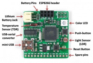
  • ATmega644 @ 3.3V, 16MHz, with CH340G USB-serial converter and Arduino bootloader.
  • 3.3V 500mA linear regulator.
  • Programming in Arduino using the on-board mini-USB port.
  • One color (RGB) LED, one pushbutton, one reset button. (New on version 1.1: one additional button on ESP8266’s GPIO0 pin, useful for firmware upgrade)
  • One light sensor (LDR), one temperature sensor (TDR).
  • One 2×4 pin header to fit ESP8266.
  • Additional pin headers for connecting external components and/or breadboard experiments.

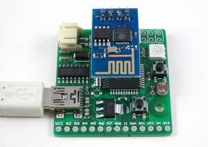
In essence, the ESPToy 1.0/1.1 is a 16MHz Arduino with some handy built-in components for easy prototyping with the ESP8266 WiFi module. Once programmed, the whole assembly can run on battery. There is also a power MOSFET on board to programmably control the power supplied to ESP. This allows you to cut off power to save battery life.

The reason I picked ATmega644 (instead of ATmega328) is that 644 has two hardware Serial interfaces. I am using one for the bootloader and USB communication, the other dedicated for WiFi. This is quite handy and allows you to use the fast baud rates. Also, 644 has twice as much memory as 328, so it’s suitable for building more complex projects.

esptoy_annotatedesptoy_2


Demos

As shown in the video above, I’ve written a few examples to demonstrate the basic features of the ESPToy:

New ESPToy 1.2:

To upload the demo Lua scripts to ESPToy 1.2, download and run the ESPlorer software. The Serial port baud rate is 9600 (default). You can open a demo script, click on ‘Save to ESP’ to save the script as a file to ESP’s internal flash memory space. The script will run right away after uploading. You can also click on ‘doFile’ to re-run the script.

  • Start-up Demo: every ESPToy 1.2 is pre-flashed with a start-up demo. Plug in a mini-USB cable, the blue LED will blink and the WiFi module will start in access point mode, creating a WiFi network with SSID ESPToy-xx. The password is opendoor. Connect to this WiFi network, open a browser, and type in http://192.168.4.1. Use the sliders to change the LED color, and click on ‘Refresh Value’ to read button status and analog pin value.
  • Hello ESPToy!: shows the Serial print function.
  • Blink LED: shows digital pin write, and delay functions.
  • Button Interrupt: shows how to set up interrupt on a digital pin.
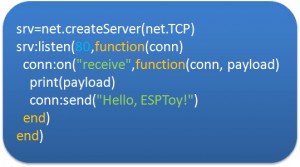
  • Hello ESPToy Server: shows a simple HTTP web server.

Original ESPToy v1.0/1.1 (retired)

  • SearchBaud: this comes handy if you forgot the correct baud rate of your ESP8266. It loops through the common baud rates, sends an empty AT command, the detects the correct baud rate by checking the result.
  • SerialCommand: this demo allows you to send AT commands to ESP8266 through a Serial monitor. Use this demo to experiment with all the AT commands available for ESP8266.
  • ScanNetwork: this demo starts the ESP8266 in AP mode, which creates a local WiFi network (the name is ESPxxxx). Use a smart phone or laptop to log onto this network, then open a browser and type in IP adddress 192.168.4.1. You will see a webpage with a list of detected WiFi networks. Type in the ssid and password of the target network, then click on Connect. The page will redirect in about 10 seconds to show the client IP address of the module on the target network. This is pretty standard approach to get your WiFi-enabled gadget to log on to your target network.
  • WebServer: this is a simple web server demo. It serves a html webpage and uses JSON and AJAX to periodically display the analog pin values. The first two analog pins correspond to the light and temperature sensors respectively, so these two values will respond to light and temperature changes. There are also three sliders to set the color of the on-board LED. As I said before, the demo can run on battery, so this can be used as a WiFi-enabled color LED light. Thinking about a simplified version of the Philips Hue? Yup, this is a poor man’s version of that 🙂
  • WebServer_SD: same as above, except this requires an external SD card slot, so that it can serve bigger and multiple html pages from files stored on the SD card.

Preparation

The ESPToy’s source code is available on Github. Check the README file therein to get started.

Serial Port and Driver:
ESPToy uses a CH340G USB-to-Serial converter. For:

On Windows, the Serial Port name is COM? where ? is a number assigned to the USB-serial chip. On Linux, the Serial Port name is /dev/ttyUSB? where ? is a number. On Mac, the Serial Port name is tty.wchxxx.

Programming ESPToy 1.2

Instructions in this section are being re-organized. For now please refer to the ESPToy 1.2 instructions in this blog post.


Programming ESPToy 1.0/1.1 (retired)
Programming the ESPToy can be done through the Arduino IDE (tested with Arduino version 1.0.6). Because ATmega644 is not a board that appears in the stock Arduino, you will need to copy the atmega644 subfolder (from the hardware folder) to the corresponding hardware folder in your Arduino’s installation directory; same with the ESPToy subfolder (from the libraries folder).

Next, launch the Arduino IDE, select Tools->Board->ESPToy, and the correct Serial port from Tools->Serial Port (see below), then select a program from File->Examples->ESPToy, and finally click on Upload

ESPToy Arduino Library:
The RFToy Arduino library can be downloaded from: http://github.com/rayshobby/esptoy. You can either clone this Github repository, or download it as a zip: https://github.com/rayshobby/ESPToy/archive/master.zip

Pin Assignments:

  • D0: ESP power (active LOW, pulled down by default)
  • D3: push-button
  • D12: red LED (pwm)
  • D13: green LED (pwm)
  • D14: blue LED (pwm)
  • A0: light sensor (LDR)
  • A1: temperature sensor (TDR)
  • Serial: USB serial TX/RX
  • Serial1: ESP8266 TX/RX

Spare Pins: D2 (INT2), D4, D15, A2, A3, A4, A5, A6, A7

Power Options:
ESPToy can be powered by USB or an external battery. There is a battery jack that fits a standard 3.7V lithium battery. In addition, there are two battery pins (next to the battery jack) — you can solder wires to connect a 3V AA/AAA battery pack. Note that the external AA/AAA battery should not exceed 3.6V (because it’s not regulated).


Flashing a New Firmware to ESP8266

Programming ESPtoy with Arduino: I strongly recommend you to learn to use Arduino to program ESPtoy, due to its flexibility and memory efficiency. While Lua firmware is easy for beginners, to write advanced programs, it’s much easier to use Arduino. Follow these steps:

  • Install the ESP8266 core for Arduino
  • Once the ESP8266 core is installed, you can select Generic ESP8266 Board, upload speed 230400, flash mode dio.
  • Before plugging in USB cable, press and hold the on-board button (on ESPtoy), then plug in the cable, and release the button. This way, the board enters programming mode.
  • Select the correct serial port (on Windows, it shows up as COMxx; on Mac, it’s generally named /dev/tty.wch…; on Linux, it’s typically /dev/ttyUSB0). Then upload.

On ESPToy 1.2 and 1.1: there is a pushbutton button (on version 1.1 it’s at the upper-left corner) — it’s connected to ESP8266’s hardware GPIO0 pin. If this button is pressed when powering up ESPToy, the ESP8266 will enter bootloading mode waiting for a new firmware. I recommend using the esptool python program to upload firmware, which is very easy to use. Specifically, in command line, run
./esptool.py write_flash 0x00000 xxxx.bin
where xxxx.bin is the firmware name.

On ESPToy 1.1, use the SerialCommand sketch to prepare ESPToy as a serial relay.


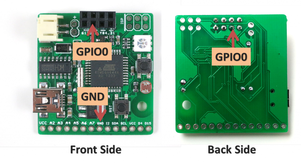
For ESPToy 1.0 (retired): to let ESP8266 enter bootloader, you need to solder a wire from ESP8266’s GPIO0 pin to ground. Specifically, if GPIO0 is pulled to ground, upon power-up ESP8266 will enter bootloader mode waiting for a new firmware from the Serial interface. In contrast, if GPIO0 is pulled up (to VCC), ESP8266 will boot into normal operation mode.

The picture below shows where the GPIO0 pin and a ground pin (any ground pin on the board should work). The wire should be soldered at the back of the circuit board. You can also connect a switch in series on the wire to easily switch between bootloader mode and normal mode.

esp_gpio0

Once this is done, you can flash the SerialCommand sketch to ESPToy, which will make it serve as a Serial relay. I recommend using the esptool python program to upload firmware, which is very easy to use. Specifically, in command line, run
./esptool.py write_flash 0x00000 xxxx.bin
where xxxx.bin is the firmware name.


Purchase Link

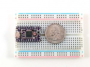
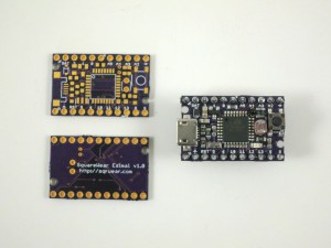
Since SquareWear 2.0 and Mini, there will soon be a new member in the SquareWear family. This is a sneak peak preview of SquareWear Esimal — the tiniest SquareWear ever made 🙂

2014-11-14IMG_20141114_123548

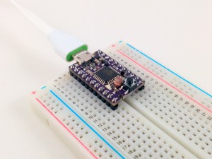
How does it differ from the other two members? First, it’s tiny and measure only 1.1″ x 0.7″. It’s designed to be small, low-cost, and suitable for breadboard experiments. It has two rows of 1×11 0.1″-pitch pin headers and can fit directly onto a breadboard. Second, it uses a micro-USB connector, which helps reduce the overall footprint. Although the big sewable pins are gone (so are the built-in buzzer and rechargeable battery), the Esimal keeps the most essential features of SquareWear — it has ATmega328 running at 3.3V, 12MHz, with built-in USB port and USBasp bootloader, light sensor (using a photoresistor), temperature sensor (using a thermistor), general-purpose button, and LED. Overall it will be a very low-cost, breadboard friendly SquareWear, for learning Arduino programming, organizing workshops, and general-purpose microcontroller projects.

IMG_0479

Since this post is a preview, I will not dwell too much on the details. Expect Esimal to be available in a few weeks time!

Introducing RFToy 1.0

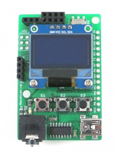
Today I am introducing the first version of RFToy — an Arduino-compatible gadget for interfacing with Radio Frequency (RF) modules. First, let me show you a few pictures of RFToy and a video introduction:

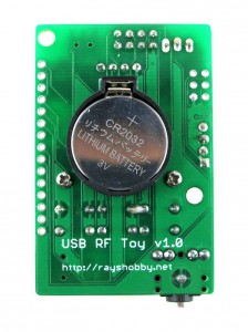
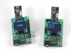
IMG_0419IMG_0428IMG_0426
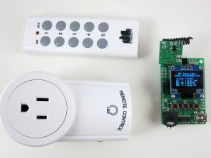
IMG_0427IMG_0431


RFToy is available for purchase at Rayshobby Store.


Features
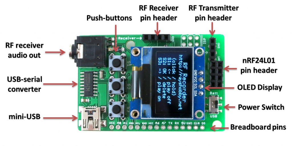
  • ATmega328p @ 3.3V, 8MHz, with CH340G USB-serial converter and Arduino bootloader.
  • Programming in Arduino using the on-board mini-USB port.
  • One 128×64 OLED display, three tactile buttons.
  • 20mm coin battery holder, and slide switch to select between USB or battery power.
  • Pin headers for plugging in 433/315 MHz RF transmitter and receiver modules, and MOSFET power switches for them.
  • 3.5mm audio jack to output receiver signals to a computer’s line-in port, to monitor RF waves.
  • Pin headers for plugging in nRF24L01 transceiver.
  • Pin headers for connecting external components and/or breadboard experiments.

So in essence, RFToy is a 8MHz Arduino with buttons, OLED display, battery holder. It’s compact (1.5″ x 2.3″) and it’s suitable for a variety of projects involving RF modules.

rftoy_annotated


Demos

As shown in the video above, I’ve written a couple of examples to demonstrate the basic features of the RFToy.

  • RF Recorder: this demo shows how to use RFToy to decode signals from the remote control of a typical wireless power socket, store the decoded signal in EEPROM, and play it back to simulate the remote control. You can store up to 7 different signals, allowing you to control up to 7 power sockets. The demo is based on the RCSwitch library, and it has a basic UI using the OLED display and buttons.
  • Wireless Temperature Sensor: this demo uses a pair of RFToys — one RFToy has a thermistor (connected to analog pin A1) and sends out the temperature reading periodically through its 433MHz transmitter; the other has a 433MHz receiver, and displays the received value to the OLED. This demo is based on the VirtualWire library, and uses the watchdog timer and power-down sleep to save battery life when the sensor is not transmitting data. A variant of this demo is also provided using a pair of nRF24L01 transceivers and the Mirf library.
  • Interfacing with Off-the-Shelf Wireless Sensors: previously I’ve written several blog posts about using Arduino to interface with off-the-shelf wireless temperature, humidity, rain, and soil moisture sensors. Since these sensors all work in the 433MHz frequency band, these demos can all run on RFToy, with sensor values displayed onto the OLED.

With the built-in buttons, display, and Arduino compatibility, there are tons of other projects you can build with RFToy.


User Manual

RFToy is open-source. You can check out its Arduino library code at http://github.com/rayshobby/rftoy, and hardware design files at http://github.com/rayshobby/rftoy-hw. Some technical details are provided below:

Note: the content on this page is published under Creative Commons Attribution-ShareALike (CC BY-SA) 3.0 License. Content reuse is allowed. If you have a project/product based on RFToy, please acknowledge my contribution. The software code and hardware design are published for educational purpose.


Purchase Link


Older Posts »