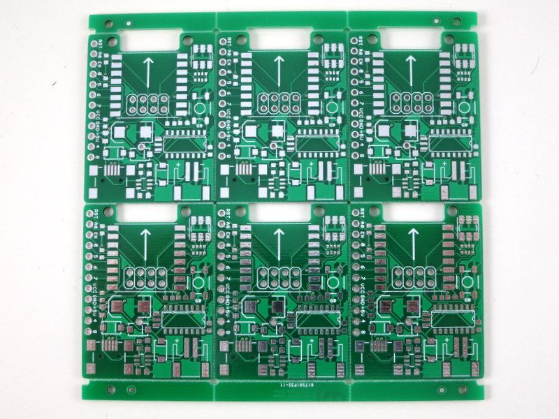
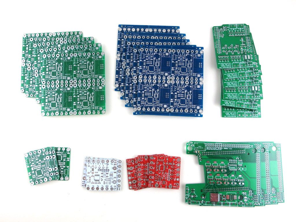
We have a number of overstocked printed circuit boards (PCBs) which I’ve listed on the shop page for sale. These are official PCBs used for our products, and are great for your prototyping need. They are all less than 40 cents each, and schematic / board design files can be found on the Rayshobby Github page (link included in each page). If you are interested, go to Rayshobby Shop to place an order. Thanks.
Since March this year, orders of OpenSprinkler have been increasing rapidly. Within a couple of weeks, we’ve done two batches of OpenSprinkler 2.3 at our local manufacturer — Worthington Assembly Inc. (WAi). Previously I have blogged about OSPi manufactured at WAi, and I’ve shown videos of their SMT surface mount manufacturing pipeline, including pick and place machine and reflow oven. This time, I was able to get two great videos of the selective soldering machine, which is used for through-hole soldering. Check the video here:
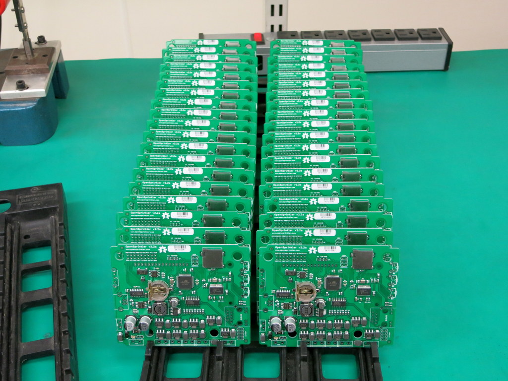
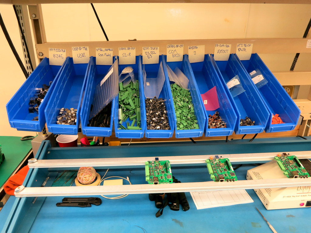
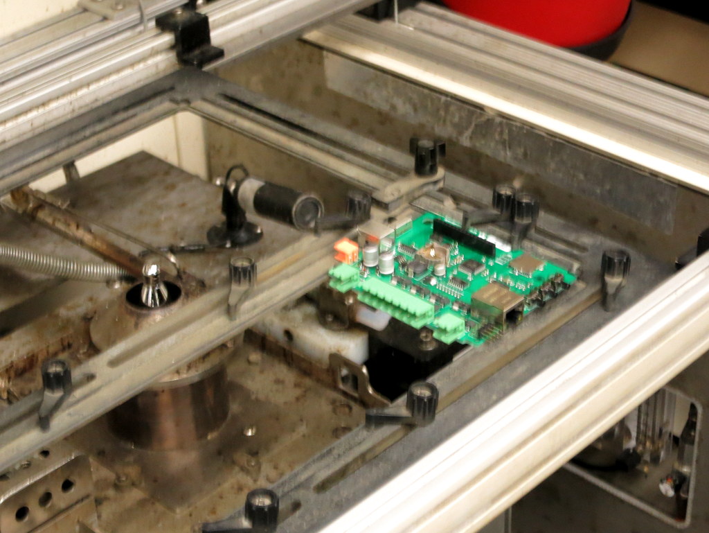
Below are some snapshots. First, before soldering, the boards are queued, and all through-hole components are hand inserted to the board,
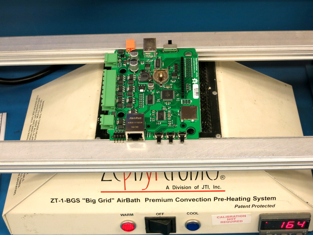
Next, each board goes through a pre-heating machine to get pre-heated, and then sent to the selective soldering machine. The selective soldering includes a fluxing phase, and soldering phase. Check the video above for details.
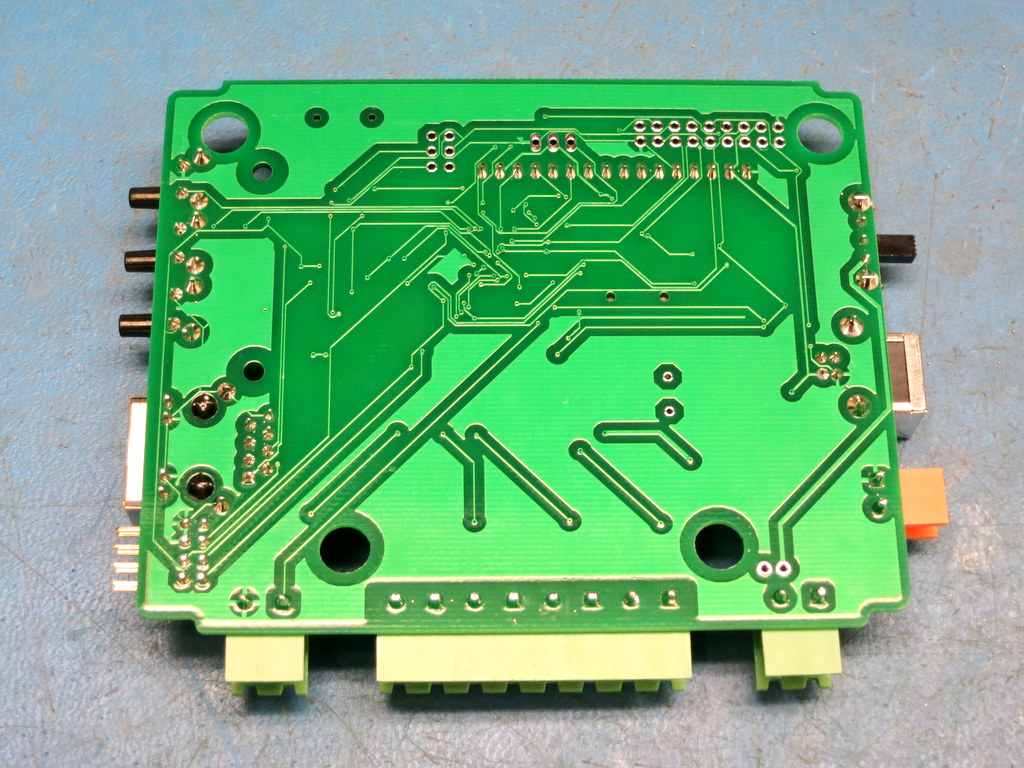
This is the result of the selective soldering. Looks very nice, and much better than hand soldering!
I realize that I haven’t properly announced OpenSprinkler 2.3. So let me give a brief introduction here. OpenSprinkler 2.3 was released ahead of schedule, due to a weird supply chain shortage issue. Basically, OpenSprinkler 2.2 was using Atmel’s ATmega644 microcontroller. A few months ago, as we were about to purchase another batch of 2.2, it suddenly occurred to me that there was a shortage of ATmega644 — our Chinese suppliers said they couldn’t source this component. Then on the US supplier websites, ATmega644 ends up costing slightly more than its next upgrade ATmega1284, which has twice the flash memory size and four times the RAM size! This is very surprising. Even today, you can see that the price of ATmega644 is no less than ATmega1284. Because of this, it no longer makes sense to stick with ATmega644, therefore we decided to immediately upgrade to OpenSprinkler 2.3, by using ATmega1284. This is pretty much the only major change between 2.3 and 2.2. Some other changes include using as much SMT components as possible, to reduce the number of through-hole components.
At the moment, the firmwares for OpenSprinkler 2.3 and 2.2 are pretty much the same. However, since OpenSprinkler 2.3 has doubled the flash memory size and quadrupled RAM size, it’s geared up for major firmware upgrades in the future. At the minimum it will be able to allow for a larger number of stations, more programs, and more data stored in the microcontroller.
So in sum, this was an upgrade that went ahead of schedule, and was due to an unexpected shortage of the previous microcontroller.
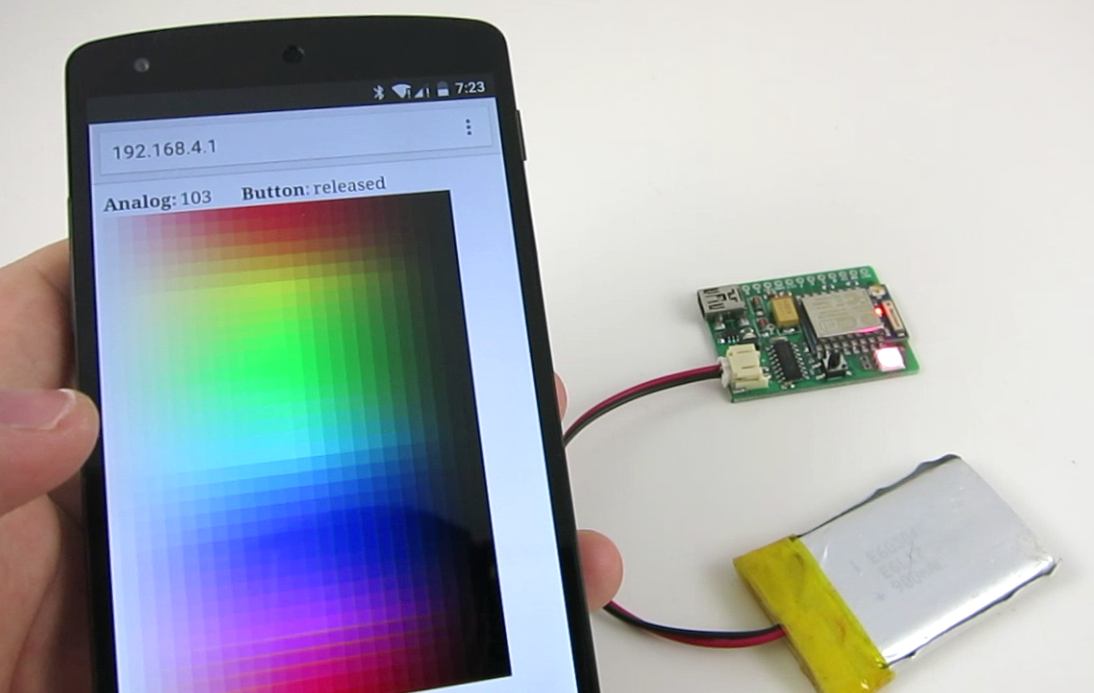
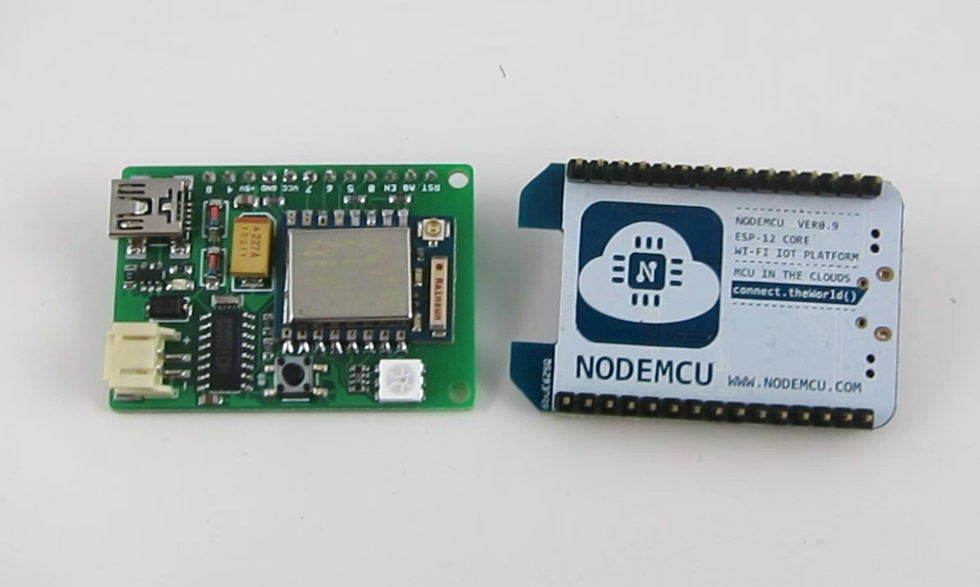
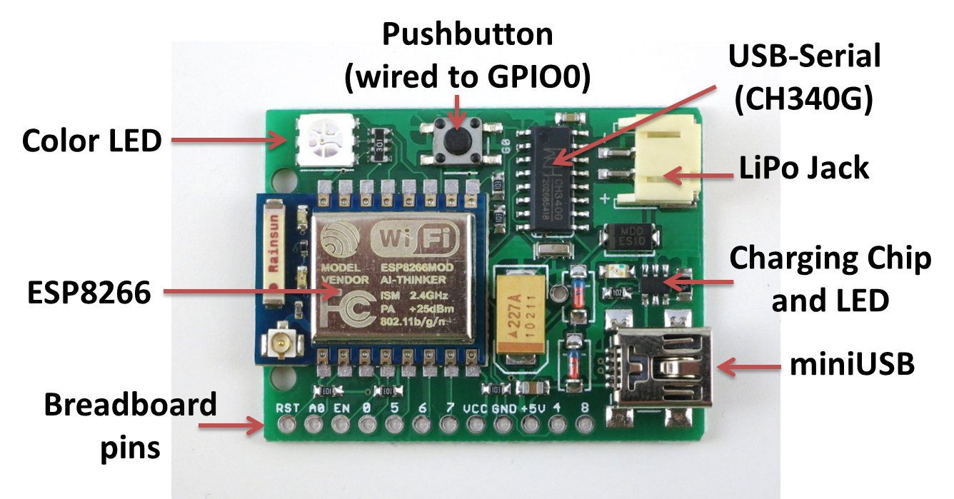
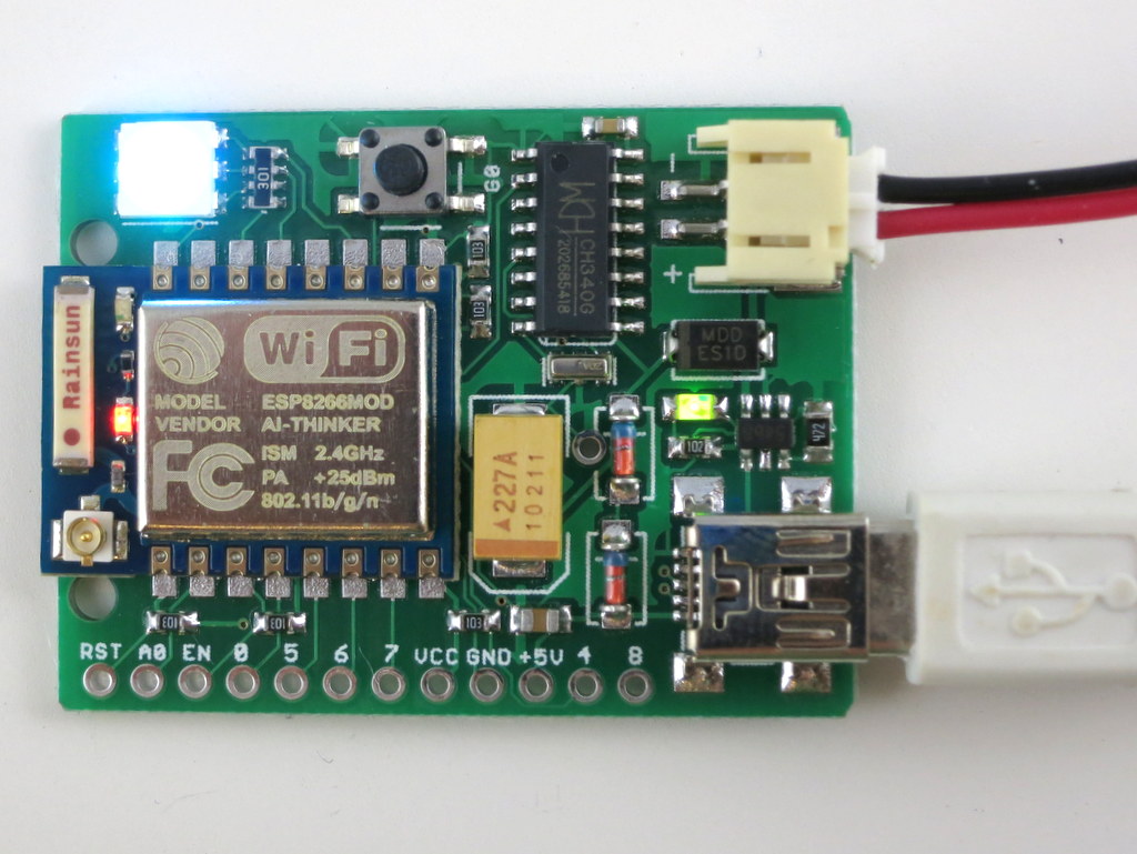
Since the first version of ESPToy, I’ve done some pretty rapid revisions. This post is to introduce the new minor revision 1.21, with LiPo battery jack and charger. As you can see in the annotated diagram below, the main components are the same as ESPToy 1.2: a color (RGB) LED, pushbutton (wired to GPIO0, so it can be used to bootload but also function as a general-purpose pushbutton), a surface mount ESP8266 module, CH340G USB-serial chip, mini-USB port, and breadboard pins. The ESP8266 module is pre-flashed with the latest Lua firmware, and a start-up demo (WiFi-controlled color LED). You can use the pushbutton to re-flash the firmware if necessary. The newly added components are the LiPo battery jack, charging chip (TP4054), and indicator LED.
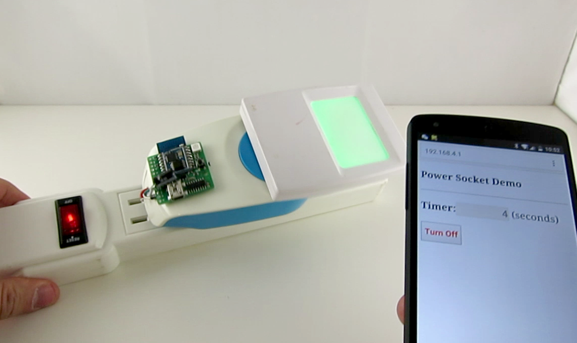
The LiPo jack and charger are due to popular requests. Since many users want to power the ESPToy with a LiPo battery, and make a standalone gadget, it makes perfect sense to add a LiPo jack. It also make sense to throw in a LiPo charging chip (the same as used on SquareWear and AASaver), to automatically charge the battery whenever a USB cable is plugged in. There is a green indicator LED which will turn off when charging is completed. The charging current is approximately 200mA.
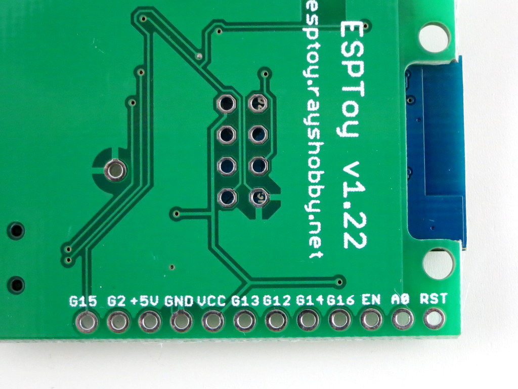
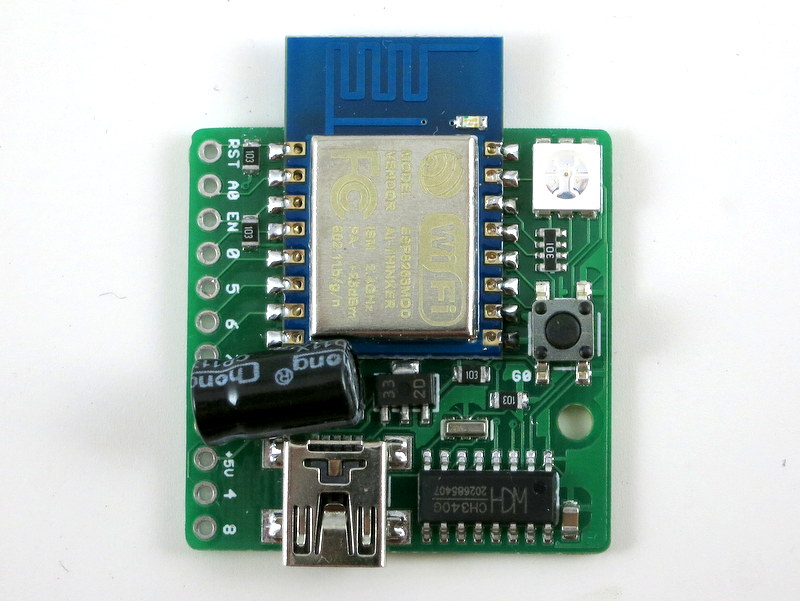
The silkscreen above the breadboard pins marks the pin numbers defined by the Lua firmware. There is one ADC pin (A0) and six general I/O pins (0, 5, 6, 7, 5, 4, 8). In case you want to try a different firmware, and need to know the hardware GPIO pin numbers, just check the silkscreen at the back of the circuit board — those names refer to the hardware GPIO pin numbers. For example, G15 refers to GPIO15. Check the image on the right above.
Another change, as you may have noticed, is that there is no LDO anymore. I got burned by a batch of 3.3V LDOs which aren’t outputting enough current. This lead to some unstable behavior (e.g. ESP8266 restarting etc.). Because ESP8266 can draw a high amount of instantaneous current, the LDO needs to be sufficiently powerful. In this new design, I’ve simply used two diodes to drop the voltage from 5V to about 3.6V (each diode drops 0.7V). In practice, since the USB voltage is often lower than 5V, the VCC is somewhere between 3.2V to 3.6V, which is within the operating voltage of ESP8266. This seems to work quite well, and I’ve not had any power-related issue so far.
I’ve recently used ESPToy at a school workshop. Students really liked it. I was quite concerned with launching 20 WiFi networks in the same room — however, it worked quite well and everyone was able to get the WiFi-controlled color LED demo to work. Given the success of ESPToy, I have been working on redesigning SquareWear as well, to make a special version called SquareWear WiFi, also based on ESP8266. More updates on that will come soon!
A little while back I released the very first version of ESPToy — a ESP8266 Development Board with a few useful on-board components like color LED, button, and temperature sensor. It has a built-in ATmega644 microcontroller, and pin headers for plugging in a ESP-01 through-hole WiFI module. Shortly after that, I discovered the Lua firmware (named nodemcu) for ESP8266. At first I didn’t pay much attention — Lua is a new language that I’ve never used before, and I wasn’t sure if it’s worth my time learning about it. At the same time I was getting tired of the AT firmware (the original firmware that comes with ESP), partly because it’s not very stable, and partly because it’s complicated to use and involves an extra microcontroller to communicate with it.
Over time I saw increasing development and community support on the Lua firmware. So I became more curious. The final push came recently: there was a supply chain problem of the ATmega644 microcontroller. I was about to purchase a new batch of ESPToy 1.1, but the microcontroller is difficult to source from my suppliers in China. I decided that I should give the Lua firmware a try — if it works, I don’t have to use an extra microcontroller any more!
That’s where I wish I had known it earlier — the Lua firmware is, in my opinion, all around better than the AT firmware. It’s easy to use, especially for writing simple web servers; it’s more stable, and best of all, it runs Lua scripts directly on the ESP module, removing the need to use an extra microcontroller. So here comes ESPToy 1.2, with a surface mount ESP8266 module, pre-flashed with the Lua firmware and a start-up demo (WiFi color LED demo):
Built-in Components. Similar to the previous versions, ESPToy 1.2 has a built-in color LED, pushbutton, mini-USB port and the CH340G USB-serial chip. The pushbutton is internally wired to GPIO0 and can be used to re-flash the firmware if needed. The way Lua firmware works is that you send scripts to it through the serial port. The module will execute the script on the fly, and return results (if any) back to the serial port. This is different from a standard microcontroller program in that the scripts are interpreted (not compiled ahead of time), much like how Javascript, Python, and other scripting languages work. This provides a lot of flexibility, including receiving and running a dynamic script on the fly!
Pin Definitions. ESPToy 1.2 internally assigns the following pins for the built-in components:
Lua pin 2 (hardware GPIO4): Red LED
Lua pin 1 (hardware GPIO5): Green LED
Lua pin 4 (hardware GPIO2): Blue LED
Lua pin 3 (hardware GPIO0): Button (active low)
Note that these pin names refer to the pin indices defined by the Lua firmware. These are different from the hardware GPIO pin numbers.
One big advantage of the Lua firmware is that it runs directly on the ESP microcontroller, removing the need for an extra microcontroller. This simplifies the hardware design and reduces cost. The module comes with 1 analog pin and several digital pins. It can do most things that an Arduino can, such as writing and reading a GPIO pin, reading an analog sensor, PWM, I2C, SPI, UART. But what it really excels is the capability of creating web services and handling WiFi connections. It also has a file system, storing scripts and data directly to the built-in flash memory. This is a huge advantage over Arduino, and it’s pretty much an all-in-one solution to build Internet of Things (IoT) gadgets. Probably the only disadvantages would be the relatively small number of available pins, particularly analog pins, and that the PWM speed is quite low. Other than these, most Arduino applications can be easily adapted to Lua scripts, but now with WiFi capability!
Lua 101. So what’s the catch? Well, learning a new language is a barrier. Lua is similar to C++ and Java, but it’s after all different, and the syntax is quite flexible, so some code may look obscure at first. To begin, the Hello-World example is pretty trivial:
print("Hello ESPToy!")
notice that unlike C++ and Java, there is no semi-colon at the end. Next, we can blink the LED on ESPToy by:
On ESPToy, the red LED is connected to GPIO2, green to GPIO1, and blue to GPIO4. The above lines are very much similar to Arduino code. Note that just like Python and Javascript, you don’t need to define variable types — the variable types are determined dynamically, so it’s quite flexible. Here is an example of a for loop:
led=2
gpio.mode(led, gpio.OUTPUT)
for i=1,10 do
  gpio.write(led, gpio.HIGH)
  tmr.delay(20000)
  gpio.write(led, gpio.LOW)
  tmr.delay(200000)
end
Next is a demo of using interrupt:
led=2
button=3
gpio.mode(led, gpio.OUTPUT)
gpio.write(led, gpio.LOW)
gpio.mode(button, gpio.INT)
function button_cb(level)
  if level==0 then
    gpio.write(led, gpio.HIGH)
  else
    gpio.write(led, gpio.LOW)
  end
end
gpio.trig(button, "both", button_cb)
This sets up an interrupt for GPIO3 (connected to button), which triggers a call back function when the button is clicked. Lua supports anonymous inline function, similar to JQuery. So you can also write the code this way:
gpio.trig(button, "both", function(level)
  if level==0 then
    gpio.write(led, gpio.HIGH)
  else
    gpio.write(led, gpio.LOW)
  end
end)
If anonymous functions are new to you, this can look a bit weird. But you will quickly get used to it, and find it convenient.
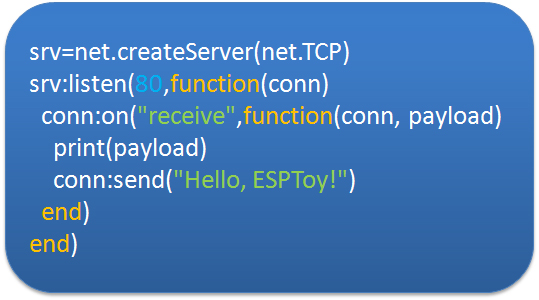
WiFi Web Server 101. While the above examples replicate what an Arduino can do, the power of ESP is in its WiFi capability and creating web services. For example, the following code creates a WiFi access point named ESPToy-xx (where xx is the last byte of the MAC address) with password opendoor:
It creates a TCP server, listening to port 80. Upon receiving a web request, if sends back a simple webpage and closes the connection. Now log on to the ESPToy-xx WiFi, open a browser and type in 192.168.4.1, you will see the webpage returned by the module. If this was to be done with the AT firmware, you would have to use a microcontroller to send commands to ESP, and the code size can easily triple or quadruple the above script. So it’s a total time saver!
File System. Another advantage of the Lua firmware is that it supports a file system. The ESP-12 SMD module has 512KB flash memory space, enough to store many scripts and data files. If this was to be done on the Arduino, you would have to use a SD card shield or EEPROM shield to provide compatible size of storage. So this is yet another invaluable feature.
Using ESPlorer. To work with ESPToy 1.2, I recommend using the ESPlorer software — a Java-based GUI for easily uploading scripts to the ESP module. It supports sending individual commands, saving scripts to files, running script files, removing files. If a script named init.lua exists on the module, the firmware will automatically execute the script upon booting. This is how the startup demo is set to run.
Re-Flashing Firmware. To upgrade the firmware (to newer Lua versions), or to revert back to the AT firmware, you can use the esptool — a Python-based script. Using ESPToy, press and hold the on-board pushbutton while plugging in a mini-USB cable. This will allow the ESP module to enter bootloading mode. Then run esptool to upload a new firmware.
Resources. You can find additional information and examples projects using the Lua firmware from the following websites:
Also, you may want to check a few tutorials of the Lua programming language to get familiar with it.
Purchase Link. In conclusion, this post is meant to be a crash course of the Lua firmware and the basic usage instructions of ESPToy 1.2. This new version of ESPToy is immediately available at the Rayshobby Shop — it replaces the previous version, and is priced at $16 ($8 cheaper than the previous version!). Give it a try, and have fun!