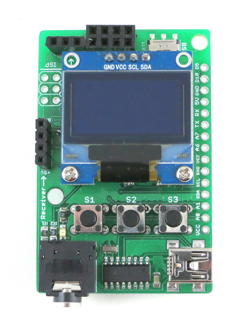
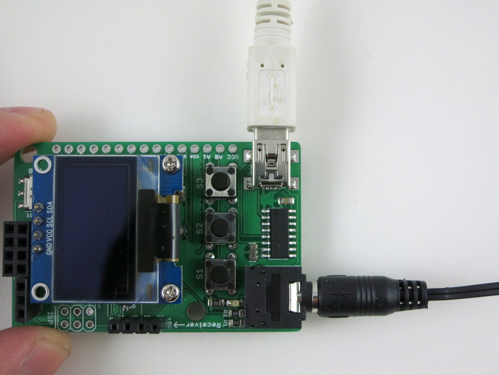
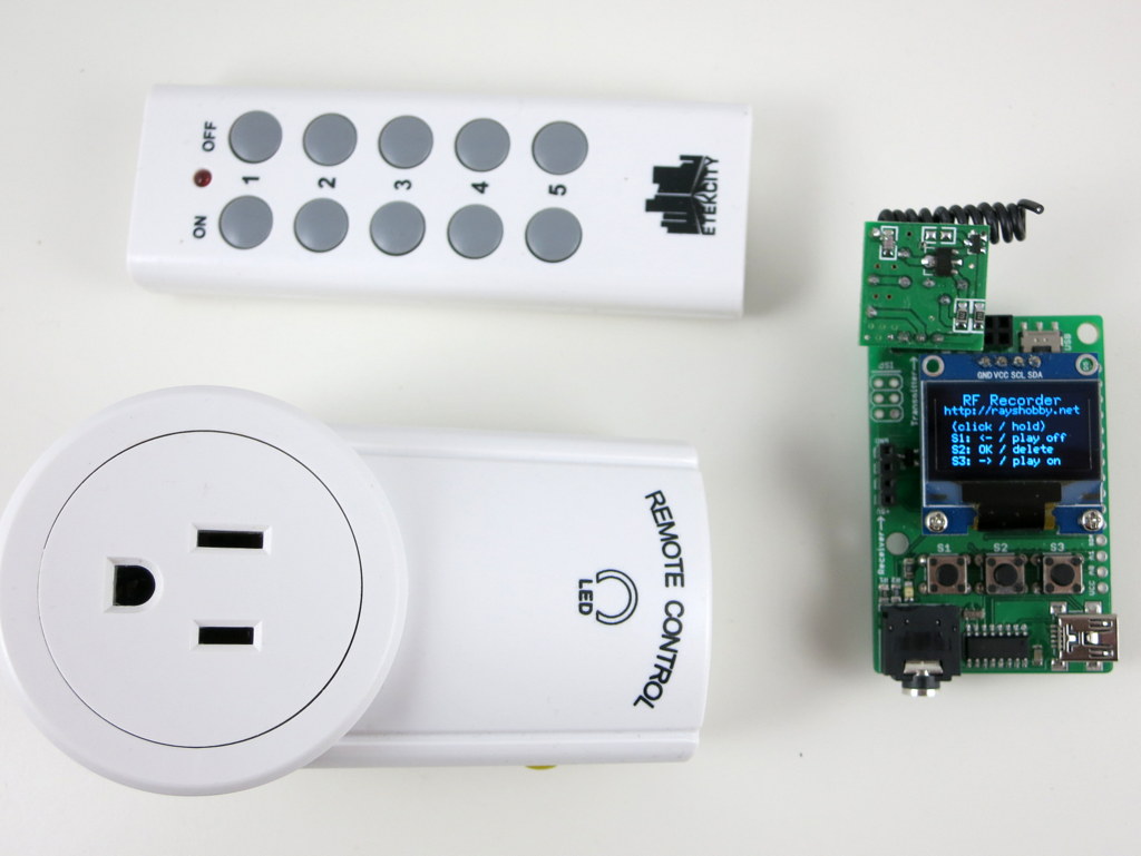
Today I am introducing the first version of RFToy — an Arduino-compatible gadget for interfacing with Radio Frequency (RF) modules. First, let me show you a few pictures of RFToy and a video introduction:

RFToy is available for purchase at Rayshobby Store.
Features
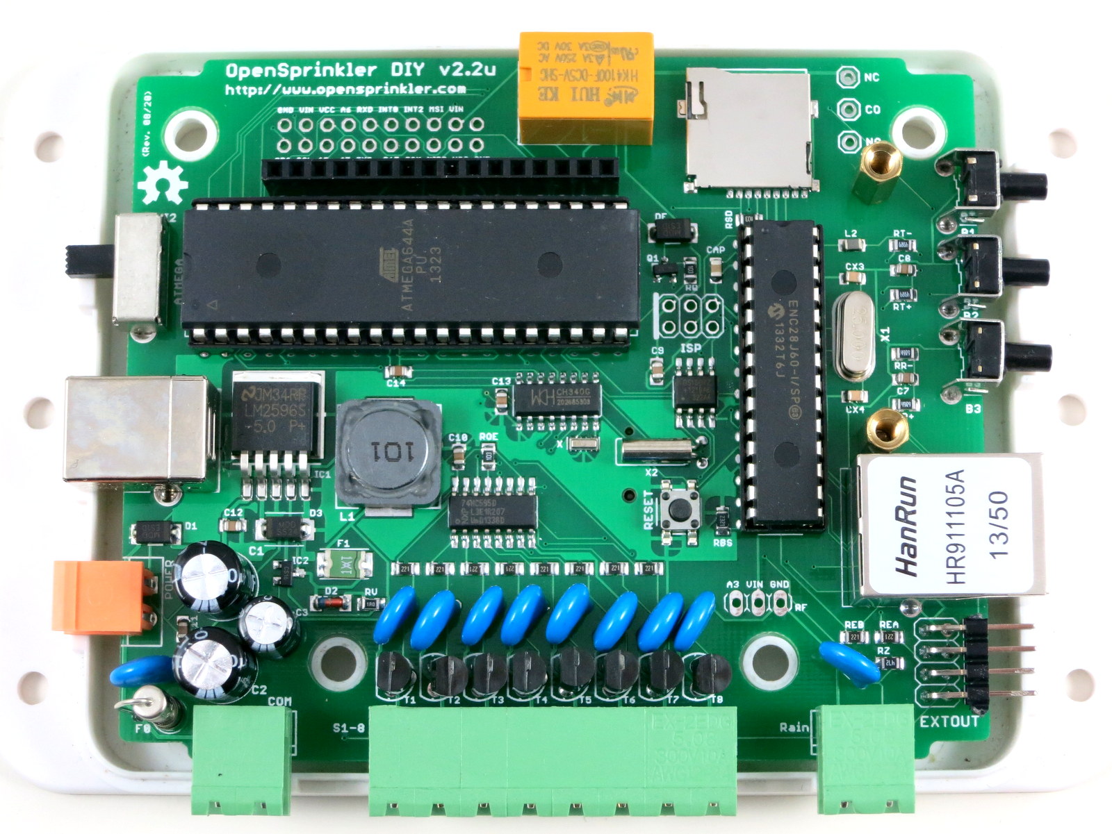
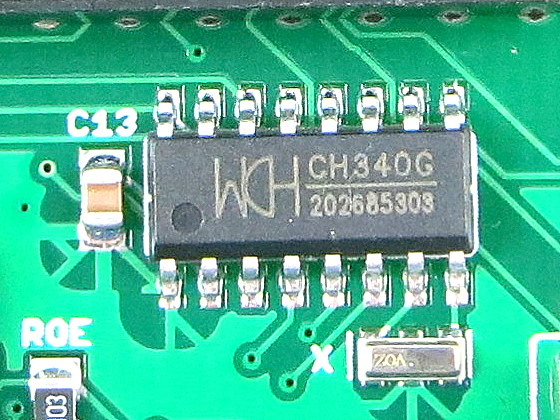
- ATmega328p @ 3.3V, 8MHz, with CH340G USB-serial converter and Arduino bootloader.
- Programming in Arduino using the on-board mini-USB port.
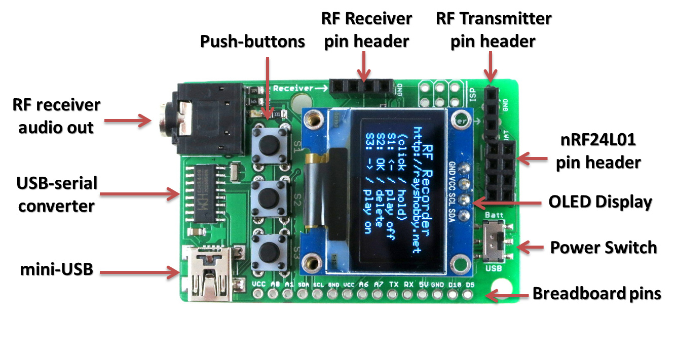
- One 128×64 OLED display, three tactile buttons.
- 20mm coin battery holder, and slide switch to select between USB or battery power.
- Pin headers for plugging in 433/315 MHz RF transmitter and receiver modules, and MOSFET power switches for them.
- 3.5mm audio jack to output receiver signals to a computer’s line-in port, to monitor RF waves.
- Pin headers for plugging in nRF24L01 transceiver.
- Pin headers for connecting external components and/or breadboard experiments.
So in essence, RFToy is a 8MHz Arduino with buttons, OLED display, battery holder. It’s compact (1.5″ x 2.3″) and it’s suitable for a variety of projects involving RF modules.
Demos
As shown in the video above, I’ve written a couple of examples to demonstrate the basic features of the RFToy.
- RF Recorder: this demo shows how to use RFToy to decode signals from the remote control of a typical wireless power socket, store the decoded signal in EEPROM, and play it back to simulate the remote control. You can store up to 7 different signals, allowing you to control up to 7 power sockets. The demo is based on the RCSwitch library, and it has a basic UI using the OLED display and buttons.
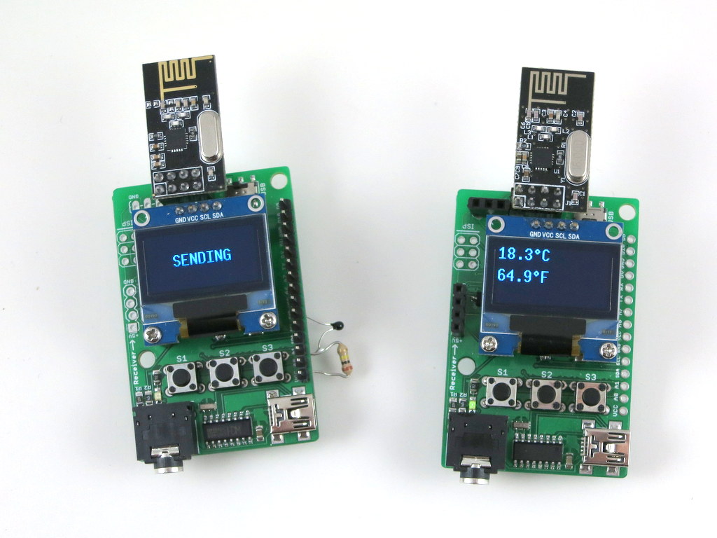
- Wireless Temperature Sensor: this demo uses a pair of RFToys — one RFToy has a thermistor (connected to analog pin A1) and sends out the temperature reading periodically through its 433MHz transmitter; the other has a 433MHz receiver, and displays the received value to the OLED. This demo is based on the VirtualWire library, and uses the watchdog timer and power-down sleep to save battery life when the sensor is not transmitting data. A variant of this demo is also provided using a pair of nRF24L01 transceivers and the Mirf library.
- Interfacing with Off-the-Shelf Wireless Sensors: previously I’ve written several blog posts about using Arduino to interface with off-the-shelf wireless temperature, humidity, rain, and soil moisture sensors. Since these sensors all work in the 433MHz frequency band, these demos can all run on RFToy, with sensor values displayed onto the OLED.
With the built-in buttons, display, and Arduino compatibility, there are tons of other projects you can build with RFToy.
User Manual
RFToy is open-source. You can check out its Arduino library code at http://github.com/rayshobby/rftoy, and hardware design files at http://github.com/rayshobby/rftoy-hw. Some technical details are provided below:
Note: the content on this page is published under Creative Commons Attribution-ShareALike (CC BY-SA) 3.0 License. Content reuse is allowed. If you have a project/product based on RFToy, please acknowledge my contribution. The software code and hardware design are published for educational purpose.
Purchase Link